 Yann Guidon / YGDES
Update : see 38. My first diode matrix
I have not been able to find a satisfying solution to my 7 segments decoding issue. It must be "dirt cheap", SMD, rather low power and low-tech.
I have received several interesting tips in the comments there https://hackaday.io/project/8121-discrete-yasep/log/26811-first-page-and-first-roadblock but it doesn't "fit". The spirit of the project is "it's better to put 50 parts at $0.01 each instead of an integrated solution at $1" (and who cares about the surface ? It's cool !).
Flashback
In my teens (like, 1991 ?) I LOVED the CD4017. Once, I wanted to display the output as a 7 segments digit. I wanted to show the current channel number for a radio project, I just push a button to change to the next channel. I looked at 7 segments decoders but they require a binary coded input, not a 1-out-of-10 decoded input.
I figured that I could decode the display with a matrix of diodes. It's more bulky but "it would be handy to know in case 7 segment decoding ICs became unavailable".
More than two decades later, the irony burns.
So back to the drawing board and it seems that I should have done it long before. Let's simply look at the conversion table :
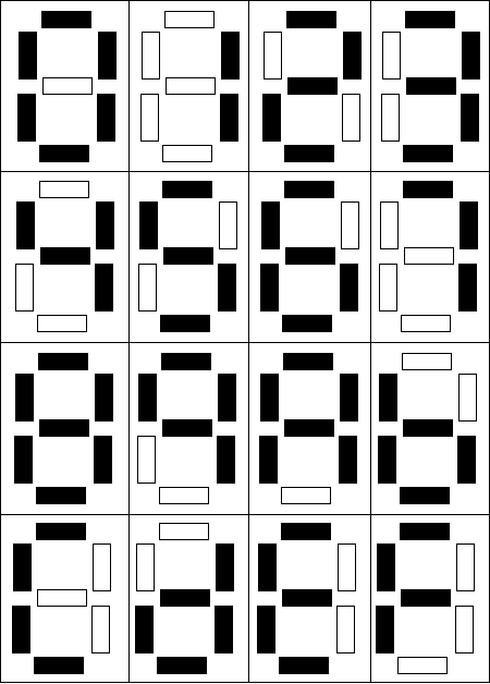 The digits are in average more on than off. So it's easier to count the digits that are off : The matrix shows that there are 33 segments OFF (vs 79 ON).
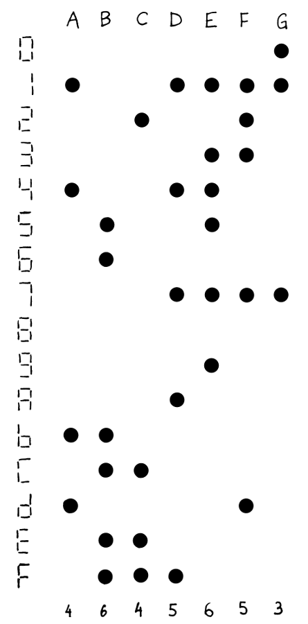
We need 33 SMD diodes and a 4->16 decoder. The design uses 74HC138s all over the place so let's use this guy. Its outputs are "inverted" (active low) and that's indeed what we also need because our logic is inverted !
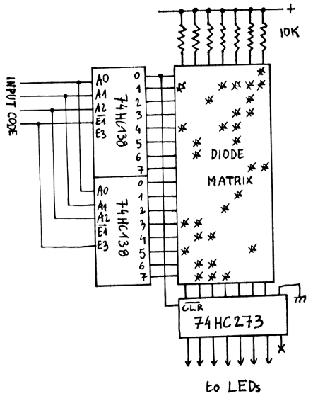
As for the parts cost : I can find 1K 1N4148 for $6, that's $0.2 for all the diodes, plus as much for a couple of '138. I don't even count the 7 pull-up resistors. Round the total up to $0,5 if you want. I don't know yet if I'll implement one or two because I need to drive 4 digits from a byte stream. But I just looked at my personal stock and I have "enough" of SMA and SMB-sized Schottky diodes for many prototypes. Schottky is better because the drop is lower so we're sure to provide a clean voltage that is less than 0.2×Vcc for the following CMOS inputs. 1N4148 might be in the grey zone but it's not a fast circuit so we have "a little margin".
One extra perk is the "leading zero" detection : one of the '138 will lower its /Y0 pin when the input is 0. This can be cascaded and control logic further down the datapath. For example it can reset a '273 and spare the energy to display 6 ON segments of "0".
Edit: the buffer is not HC273 but MM74ACT273, at least for the prototypes, due to availability, tighter VinL and VinH, and better output current. The Fairchild HC273 will be used when driven by other HC logic (or compatible).
I'm not the first to implement this method. I keep reinventing the wheel and things like this decoder have been done for ages.
If only I had taken the time to lookup "diode matrix rom" on google ? It's only a matter of finding the right keyword...
http://www.instructables.com/id/TOD-Diode-Matrix-ROM-intro-7-segment-display/?ALLSTEPS (uses inverted logic like here)
http://hackaday.com/2013/10/18/making-a-diode-matrix-rom/ (a comment there and a link to http://josh.com/notes/bitlybot/ make me contemplate a version with red LED instead of Schottky. I have many 0603 LED so it can replace SMA/SMB diodes but the output must be "level shifted" because low level would be around 2V)
http://www.cca.org/blog/20120222-Diode-Matrix.shtml
http://atariage.com/forums/topic/226940-diode-matrix-rom-for-atari-2600/
etc.
Discussions
Become a Hackaday.io Member
Create an account to leave a comment. Already have an account? Log In.
OOOOps ! Digit C is missing a dot for the G segment.............
Are you sure? yes | no
Fsck Google. Take pride in what you've accomplished without that crutch.
Are you sure? yes | no
Thanks eric ;-) Words to live by. Yet that crutch is often invaluable :-D
Anyway, it's awesome what others have done just with diodes...
I feel I'm walking in our predecessors' steps !
Are you sure? yes | no
BTW...
fsck: filesystem "Google" not found
Are you sure? yes | no
Interesting, what version of fsck are you using? Mine spits out usage "help." But of course you know what I *meant* by "fsck" right? -- haha, nevermind ;)
Are you sure? yes | no
Should I ? :-D
Are you sure? yes | no
Actually those are 4 diodes in 2x2 configurations. Way ahead of you. :)
Are you sure? yes | no
oh I thought you typoed "2 x dual pairs"
Progress can't be stopped... ;-)
Are you sure? yes | no
BTW you can lower the part count some what by using switching diodes in common cathode. e.g. BAS40DW-05 that comes in 2 x dual pairs of schottky diodes in a SOT363 package
Are you sure? yes | no
Hi,
Yes you're right and I even thought about this but I already have the SMA and SMB parts. The dual diodes may not be used everwhere because some lines have an odd number of connections. One can still "just forget" one input of the package or complement with SMA "dust".
But I'm concerned about the slippery slope here. You start integrating two diodes in a single package, then what's next ? 4 diodes ? A whole transistor ? Several transistors ? A whole computer in a 3-pins TO-92 ? The end is near, I already use a microcontroller in SOT23... :-P
Are you sure? yes | no