 Yann Guidon / YGDES
As I was entering the schematics of the keypad, I realised that I didn't take a certain situation into account.
The RC network on the common sense signal works both for debouncing and as a pull-up. Due to the hysteresis, there can be a "ltitle delay" between the keypress and the actual assertion of the signal. In the rare case when the key is pressed at the end of the switch's clock scan cycle, the event might be recorded for the next key instead of the actual pressed key. This could have annoying consequences.
A smaller capacitor reduces the window of eventuality but the capacity should not be too small either (for EM sensitivity reasons, it's going to pick up quite a lot of noise).
Another approach is : reverse the logic and use multiplexers instead (74HC151 for example). It's a pretty interesting idea but it does not fit nicely with this specific keyboard. The diodes would be replaced with resistors and power would be drawn proportionally to the number of simultaneously pressed keys. Other practical factors are the much better availability of the 74HC138 (it's cheap) and the board is already half soldered...
OTOH the '138 adds a tiny window of uncertainty since two consecutive output signals could overlap, even for mere nanoseconds.
But I have found a solution that is rather simple and elegant, as it uses only one additional 74HC138 to solve these problems.
The 5th '138 decodes wich of the 4 others is being active and also how long. Usually, you can "gluelessly" connect 3× '138 and decode 24 codes without additional logic, thanks to the 3 enable inputs. Going to 32 codes requires one additional inverting gate, another DIP chip with only one used gate.
The new '138 takes over the decoding task and is enabled only when 3 LSB of the counter are low. This shortens the output pulse to 1/8 of a keyscan cycle and gives enough time to the RC network to recover (without effect) before checking the next key. Implicitly, the '138 is used as a OR gate with multiple inputs. A side effect is the reduction of the total power draw because current flows through the resistor for a shorter time, and only when the key is pressed.
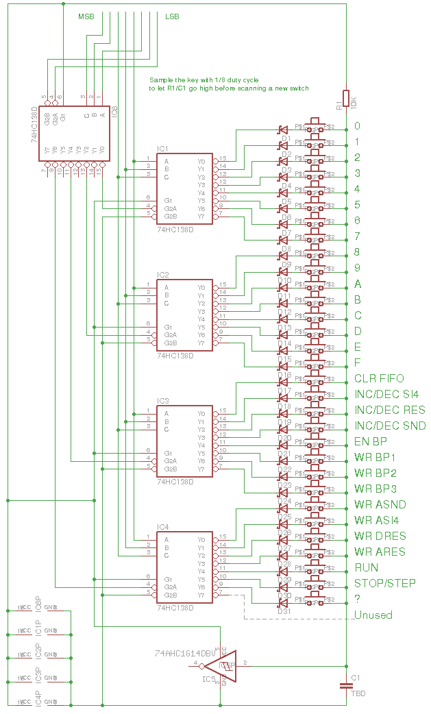
Now the trick is to ensure that the capacitor is recharged fully at the end of this cycle. Since the pull-up value is fixed (10K) I have to determine the proper value of the capacitor. More experiments will follow, with the 'scope plugged, because I'm not sure I can model the circuit accurately enough and the schmitt trigger adds some uncertainty anyway (trigger levels can vary a lot).
Discussions
Become a Hackaday.io Member
Create an account to leave a comment. Already have an account? Log In.