 Yann Guidon / YGDES
With the experience gained from de #DYPLED subproject, I can easily design custom LED displays and the register names (on the P1B board) is a great application of the principles. The ingredients are the same : a large parallel Flash chip (1M×16), 4014 type LED (long, narrow and thin) for the segments, some multiplexing (one 2N7002 for the low-side driving of a group of LED), a binary counter to sequence all that (taken from the main clock divider) and one mode bit (to select between hex display and symbolic name).
P1B displays 3 buses: the result bus and the SI4 and SND source values. That's 3×4 bits. Add 2 or 3 bits for multiplexing, one mode bit and the address bus is under-utilized.
The 16 bits of output are used for 2 7-segments displays, leaving 2 unused bits. I'd like to "save" one more bit so the Flash directly drives the MOSFET's gate and saves a demux chip.
The rightmost digit displays the usual Hex numbers. The leftmost displays only 4 symbols, necessary to write the names Ax, Dx, Rx and PC. There should be a way to save a bit somewhere.
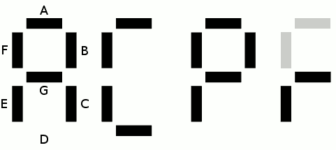
A first visual examination shows that the A and F segments are on at the same time so they can be wired in parallel. This saves the needed 3rd bit, without having to resort to external logic gates. Furthermore, the segment D is the inverse of the segment G but this would require an inverting gate.
In the end, decoding the register names uses only one Flash chip and 3 2N7002 :-)
Discussions
Become a Hackaday.io Member
Create an account to leave a comment. Already have an account? Log In.