 Yann Guidon / YGDES
Some of the boards need a 3.6864MHz source. This frequency must be magic because I often end up using it !
For another project, I gathered all the parts (in ample quantity) that make a discrete oscillator :
- 20pf cap
- 6-20pf adjustable cap
- 1M Ohms feedback resistor
- Fairchild NC7ST04 inverter gate
- Abracom 3.6864 MHz Xtal
This project does not need an extremely accurate clock, asynchronous serial links can accept up to 1% drift, so the adjustable cap is not used here. I'll just make sure it oscillates in the expected frequency range, determined by my not so sophisticated tools' precision.
The NC7ST04 is similar to HCMOS and draws less than 10µA (1µA typical) so it's "low power" though it is rated for 5V supplies. Will it still work at 3.3V ?
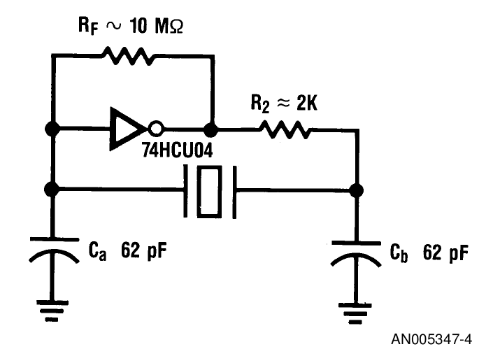
I'll use the standard Pierce topology https://en.wikipedia.org/wiki/Pierce_oscillator with help from Fairchild's application note www.fairchildsemi.com/an/AN/AN-340.pdf A tl;dr version is also found at http://www.z80.info/uexosc.htm
My bias resistor is 1M instead of the Fairchild-recommended 10M but the above picture says it's not important (it might just increase the startup time, I suppose).
The series resistor would be in the 10K Ohms range, since the following design uses an unbuffered gate, R2 can be increased (this further shields the loop from external capacitances and transients).
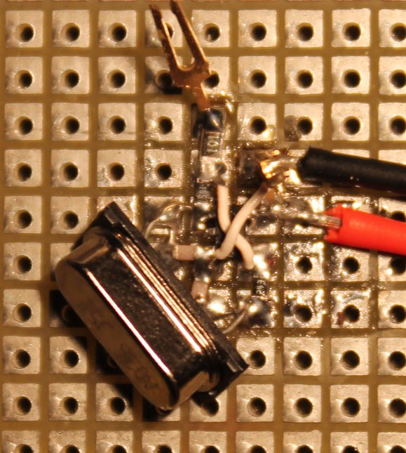
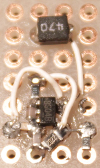
The parts are not very visible but they are all there :
The oscilloscope shows that it works but the waveform should not be considered accurate (lousy probes, lousy scope bandwidth...)
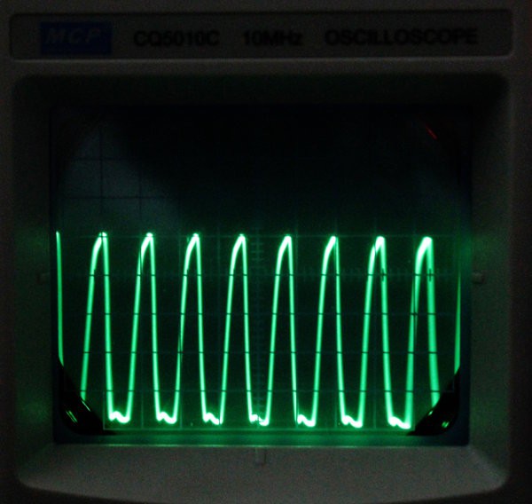
Some measurements :
- The circuit resonates (catches the fundamental) at around 1.8V (2V is safe).
- My crude frequency meter says "3.69MH" so it is well in the 1% ballpark.
- Current @3.3V : 1.6mA, 5V: 2.6mA (10× better than more expensive canned oscillators)
Conclusion : success !
Bonus points : cheap, no black box, surface mount, easy sourcing of the parts...
20151028: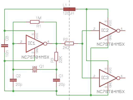
I added a couple of buffers to totally decouple the ocillator and keep it undisturbed. More buffers might be added if/when needed, probably one per board.
20151029
It seems that the output resistor R2 is too high, or something like that. I reduced it to 200 Ohms to get a half-decent waveform. I don't know if it's my 'scope or my probes or the resistors ?
OK it was the probe. It turns out, X10 mode gives a much better waveform. 2K2 is fine as long as the output is very lightly loaded.
This little experience shows again that clock buffers are really required. Given the higher value of R3, R2 might even be useless if the buffers are less than one cm away.
By the way here is the circuit before I soldered the supplies and the quartz.
Discussions
Become a Hackaday.io Member
Create an account to leave a comment. Already have an account? Log In.