 Yann Guidon / YGDES
After my last "creative moment", I visited my cave again to find a suitable mouse. They were there, in their box, waiting for my eventual return...

I couldn't find any scrollwheel mouse, unfortunately. And there are mice I don't want to hack (such as one almost perfect SUN mouse).
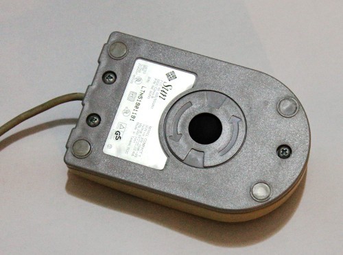
However I have found a mouse that almost fits the criteria :
- 3 soft buttons
- ball with optical quadrature wheels
- 3 easy to use screws
- weird cord/interface so I'm sure I'll never use it again
- SUN logo for extra "wow" factor and skullz!

Indeed, it was only waiting to be hacked. These screws were meant for this!

The board is highly "hackable" !
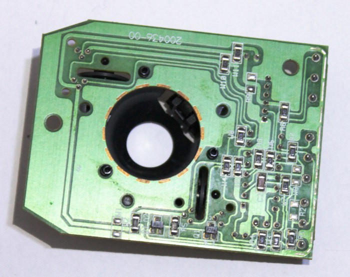
I might be able to collect data from the sensors, I just need to turn the 'scope on :-)
There is no scrollwheel but I change the interface a little bit :
- Left button : step/pause pulse
- Right button : run/start pulse
- Middle button : enable the optical wheels to send pulses
The internal logic "hack" is pretty simple : XOR all the 4 optical outputs to combine X and Y wheels (so you can make circles with the mouse to send continuous commands), AND the train of pulses with the middle button, OR the result with the left button. BTW there is no need of a AND gate because the middle button can be rewired to let the signal pass.
I'll need to do some debouncing on the 2 other buttons but there is no black magic there. Schmitt triggers with a small RC will do the work.
I suppose that the mouse works with a 5V supply... What else could it be ?
(note for later: stop guessing and read the f*ing label on the back)

Acceleration
The mouse is pretty sensitive, a tiny move can send several pulses. This is why most software implement "acceleration", where the movement creates an exponentially proportional effect, to reduce fatigue (and because we humans work a lot logarithmically).
What electronics can do that ? Well, it's at least possible to switch dynamicly from single speed to 4x speed with a few gates and some analog parts.
Each optical wheel creates a pair of signals with 90° phase.
- if you want "simple" speed, use one of the signals.
- if you want "double speed", XOR both signals.
- if you want "quadruple speed", XOR the signals from the X and Y wheels.
- You could even go "octuple speed" if you triggered a pulse on both edges of the resulting signal.
The simple strategy now is to go from "simple speed" to "double speed", on both wheels, with two different speeds for X and Y wheels, so they combine easily and with a duplicated circuit. The X wheel will go faster at a certain speed, the Y wheel will also double speed at a larger speed, so both combined will make an almost smooth curve.
The key to going from one speed to measure the frequency of one of the quadrature signals. If the frequency is higher than a set value, the quadrature signal can be combined with XOR.
The new challenge is to measure the frenquency, or detect that it is above a certain threshold. A RC network will work if we add a diode to make it asymetric (or else the accumulated charge will Vcc/2). Yes, it's a cheap "retriggerable monostable".
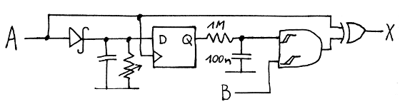
When a half cycle of the signal has passed, while the signal was high and C is charged though the diode, the discharge cycles starts. C empties through the resistor and the final value is sampled by the D latch. The Q output is again RC-filtered and fed to a Schmitt-triggered gate, because I can imagine that at certain speeds, many spurious spikes will artificially increase the number of output pulses. This circuit makes the transition smooth.
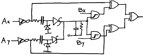
The whole circuit looks like this and generates a burst of pulses when the mouse moves on both axis.
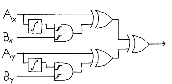
Maybe I should "share" the integrator between both channels...
I should have known in advance that even something as simple as buttons would not be so simple.
Looking at the IC's pin with the 'scope, I see the button is polled during 20µs every 16ms. If I press the button, the delay is much shorter, then returns to 16ms after 2 seconds... The short delay also comes back when I keep the button pressed continuously.
From what I imagine, there is a common "sense" pin, with a 10K pull-up resistor, and other 3 pins are driven low in sequence, one for each button. If the common pin is going low, then the corresponding button must be pressed. No complicated debouncing and it saves energy...
But this is not what I want. I'll have to rewire the buttons...
A 60Hz clock source is handy to have but it's not really useful in this situation.
The plan is simple : for the left and right buttons, a 100K pull-up each to 5V. The buttons short it to 0V, a small cap reduces the bounces and the level is inverted by 2 gates of 74LVC1G14, with its Schmitt trigger input.
For the middle button, I will connect it directly in series with the XOR output of the above schematics. This XOR is then combined with another XOR with the left button's output so both can be pressed without harmful interference (if will only create more pulses).
Testing the phototransistors gives the same result : the inputs are polled, slowly then faster while there is some activity.
It would be easier to desolder the DIP chip.
Update 20151026:
As @esot.eric noticed, there is a "startup problem" in half the cases.
Suddenly I realised that I was doing a "high pass" circuit, so there should be a capacitor in series. This is what would block the DC condition that Eric identified.
Since we play with logic levels, there are 2 fronts and we can make a positive pulse with a diode. But if the diode directly follows the capacitor, there is no return path for the current. Another diode is required, just like in a charge pump.
A series resitor is required in series with the capacitor, to reduce the output current of the 74lvc14. This is also that current that will be flushed through the integrator resistor anyway...
I have shared the integrator with both channels, I think it's better (fewer parts, isotropic behaviour). I should check the leakage input current of the following ST gates because that could influence the time constant...
Oh and to save power : the whole circuit would powered on when the middle button is pressed. There might be spurious pulses though...
Discussions
Become a Hackaday.io Member
Create an account to leave a comment. Already have an account? Log In.
@K.C. Lee, @esot.eric : I hope this answers some of your questions :-)
It's not a critical application or circuit but a nice little brain teaser, that will certainly evolve as I use the system. Stay tuned to the new adventures of mousekenstein ;-)
Are you sure? yes | no
Ah Hah! Brain tried to parse the diode-R-C filter yesterday and completely failed. I get it now, interesting. So the first circuit basically passes through A, only, until A reaches a speed determined by the diode-R-C filter... Then, when it does, it switches to "double-speed" by XORing A and B.
The diode-R-C filter is one I'll have to throw in my bag-o-tricks. But what when the mouse is stopped, and A is high for some time... Then there'll be a "burst" at the beginning, but only as long as the D-R-C filter holds a charge, so maybe only one or two steps... I'm vaguely foreseeing a bit of hysteresis in the speed-detection, which could be an interesting effect (or maybe completely unnoticeable).
Are you sure? yes | no
You nailed it ! :-)
Your startup comment with A high is a condition I hadn't considered. My initial reaction is that another monostable would be required. But that's a bad reflex. Second thought says : since it's just a "sort of VFO"... it's simple as a series capacitor !
Damnit, why didn't I think about it before ?... It saves several parts :-D
I'l have to make the schematic again.
Thanks for your comment, which made me think it further and it made a simpler, better circuit ;-)
Are you sure? yes | no
There, it's updated. Next time I'll draw the schematics directly with the Wacom instead of sketching, redrawing on paper, photographing, editing etc... it's getting out of hand :-D
Are you sure? yes | no