 Yann Guidon / YGDES
The keyboard is working, and it is working well.
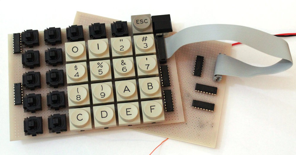
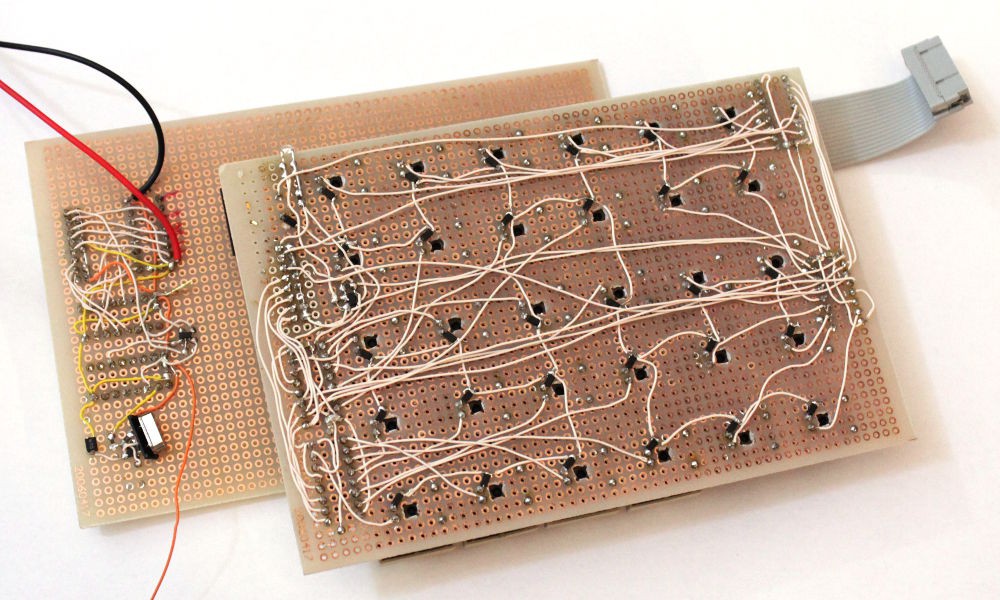
OK there were a few gotchas like a diode that was soldered in reverse and a chip with the GND pin connected to VCC but these were quite easy to spot.
The Schmitt trigger has been refined and I'm satisfied with it. Each 74HC138 outputs a pulse that lasts about 70µs, repeated every 550µs. With 15K Ohms and 10nF as RC filter, the HC14 outputs a 200µs pulse, with enough headroom until the next pulse (>300µs). There is no risk of wrong keycode. This RC filter also removes some noise pickup on the sense signal (observed when a key is pressed).
Using CMOS (mostly CD4000 and sn74lvc1G) has two great benefits. It starts to work at about 2V and the current draw is very low. I will probably use the same power supply for the TIL311 and the rest of the P1 circuits so I tried at 3.5V, the keyboard circuits draw only 0.6mA (yesssss 600µA). When a key is pressed, a white LED shines a bit so the current reaches 870µA...
Under 5V, the working "Off" current is 1.07mA and the LED increases the "On" current to 1.56mA. There is probably a better noise immunity but 3.5V seems to be a good working voltage for the rest.
Slowly but safely, I'm approaching the BMOW territory...
Now is the time to design a proper power supply, tie the scan code to a TIL311 and work on the latch strobes/pulses...
There is enough room on the clock board to add the serial receive logic, as well as the FIFO and the command multiplexer. I would like to add more input circuits later, such as the mouse of course, as well as a hardware assembler... so 4 byte inputs must be selected and correctly sequenced.
Discussions
Become a Hackaday.io Member
Create an account to leave a comment. Already have an account? Log In.