-
Yet another description of where I do not want to be
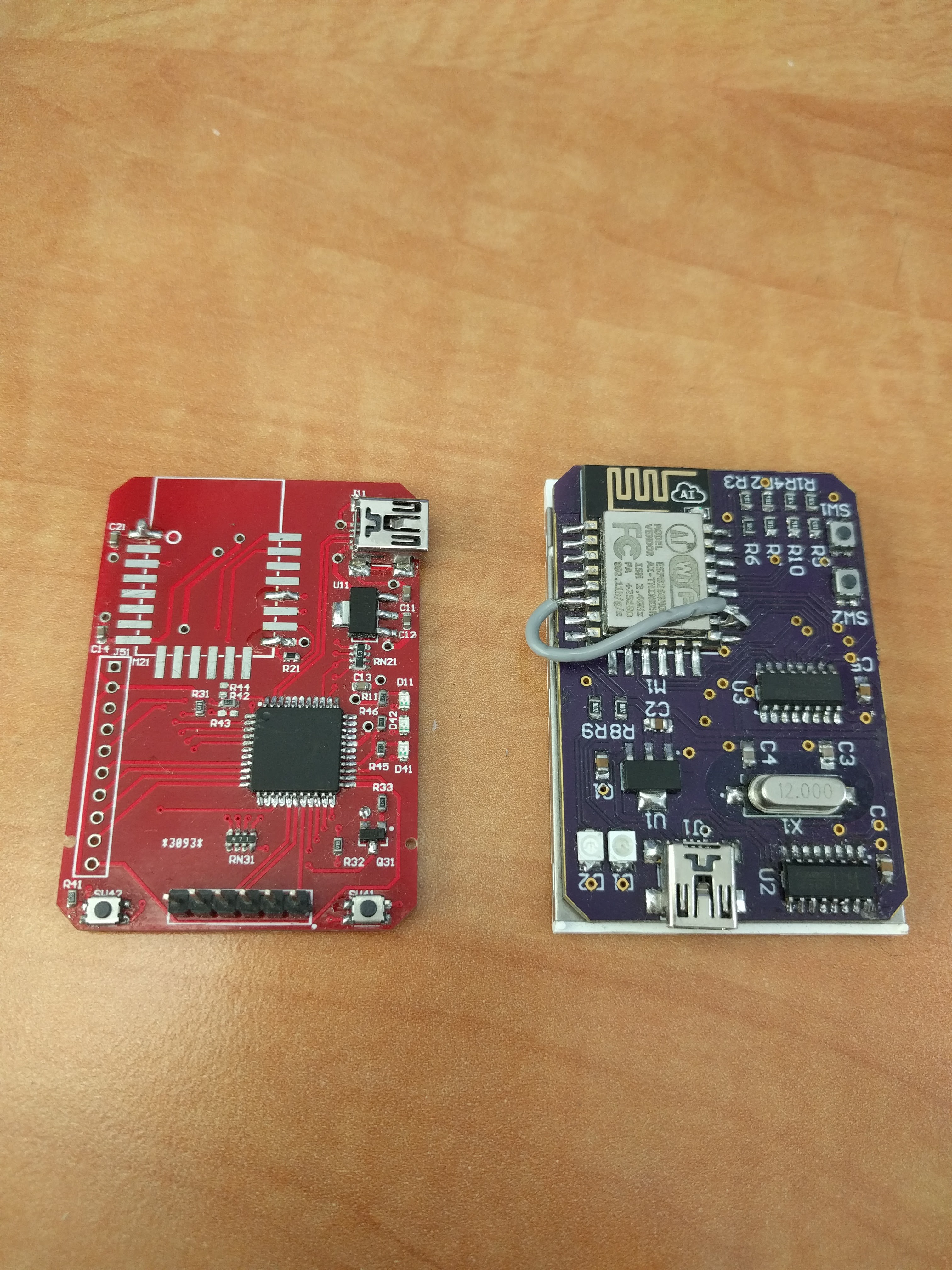
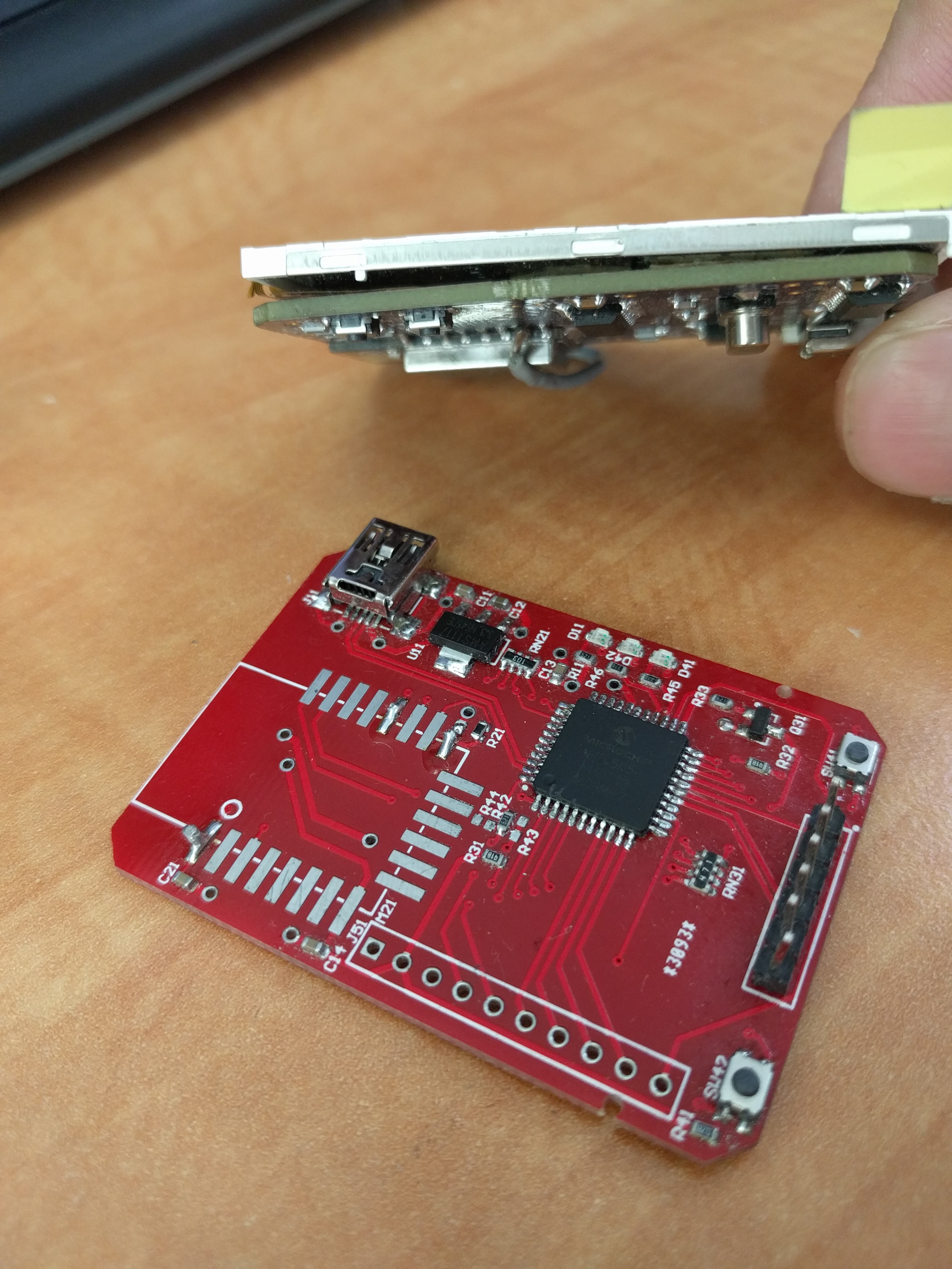
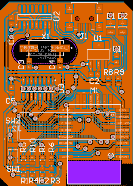
10/18/2017 at 21:56 • 0 commentsHere are a couple pictures of R2, the latest, greatest version. Compare it to R1 on the right.
![]()
![]()
The largest glaring difference, as I hinted at in the last log, is that I put a PIC microcontroller on there.
It has an open source USB stack, plenty of I/O, is mature, and I know how to use them very well.
The idea was to use it as the main processor, just handling simple wifi transactions with the ESP8266. Stretch goals would have the PIC programming the ESP8266, and maybe vice versa, too.
That single-handedly eliminates the CH340G USB-UART chip, the serial-parallel shift register for driving the parallel LCD, and the WDT/poor documentation headaches of the ESP8266.
After initial bringup, it's just been sitting on my bench, however. Staring at me. Since then, I've been collecting little snippets of Digikey part numbers, ideas, and technologies that will be incorporated into R3.
But for now, I think I will finish getting this up and going as desired. I previously wrote a quick LCD driver for a PIC dev board I have, so I'll transfer it over here, solder the LCD ribbon on, and write some image serialisation code between the two micros.
Perhaps R3 will use the ESP32? It solves a few of the problems neatly, and soon ESP-Mesh will be released.
-
I forgot to write a thing
10/16/2017 at 23:56 • 0 commentsPrototyping aw yeah.
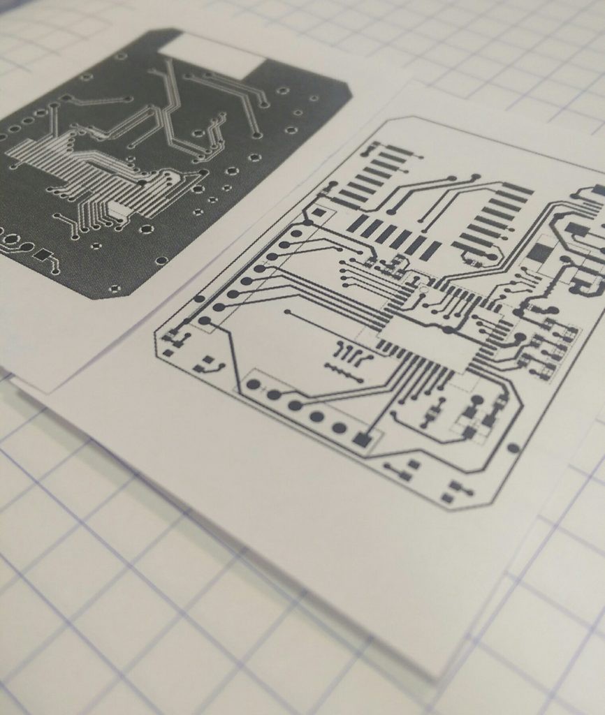
There's a bunch of work I did for that last log that I didn't post. How uncharacteristic of me. The following was written on November 6th, 2016 and posted elsewhere:
After R1, there were some things that I was planning on changing for the next respin. R1 just to get some hardware in my hands and start writing code. This next one is all about the cleanup.
The last version of this project works... Poorly. The code in the test folder is stuff to help me prototype, before I got to a working model. Originally, I tried writing an LCD driver in Python for the Raspberry Pi GPIO, but the output seemed super unreliable. Instead of taking the time to troubleshoot why, it was faster to port that code onto a PIC dev board, which worked great.
Once I had a known-good LCD (using the shift register), I finished soldering up the rest of the board and tried to bring up the whole board. It never quite worked properly, and here's why!
When I was first drawing my schematic, the most common ESP8266 module was the ESP-12. Right around that time, November of 2015, the ESP-12E had just come out, with a bunch of extra pins. No one knew much about this at the time, but the conventional wisdom suggested that it was safe to include them in my design, allowing me to get away without using an additional microcontroller. Turns out these extra pins are associated with the flash memory, and using them willy nilly causes strange reset issues. Guess what kept happening when I was trying to test my fully populated board?
So before a complete rethink was in the cards, here was the original plan for revision 2:
- The LCD has two little mounting tabs on the sides. An appropriately sized via to accommodate them will make the LCD fit better and prevent wobble
- One of those mounting holes will interfere with the switches. Move them somewhere else. Specifically on one of the short edges, because the current location causes damage to the LCD when the buttons are pressed while the screen is face down on a table
- Silkscreen for momentary switches to include functions (RST / PROG)
- Add in the clever circuit that the NodeMCU group uses to enable button-less programming
- Remove all unnecessary resistors:
- R7 connected to LCD_RST
- R10 connected to LCD_RS
- Change LEDs to 0805 or something similar. I'm using 3528s, and they are huge and super bright and look out-of-place
- Change user-settable LED to connect to a pin that is not GPIO16. Apparently some manufacturers (not mine) connect it internally to the ESP8266 reset pin
- Change all the SIPO shift register pins from bit-banging to use the ESP serial ports - Should be faster, and allows me to...
- Change requirements from an ESP-12E module to just and ESP-12, which has fewer pins
- Break out extra ESP pins to some unpopulated pads for future hacking
- Break out LCD touchscreen pins for future hacking
- Add more testpoints for debugging (and future hacking)
- Big decoupling cap
Some of these ended up making it in, but the new system design deprecated other points. So what's new in R2? Stay tuned to find out!
![]()
-
Oh, those Russians
11/16/2015 at 16:20 • 0 commentsObviously I've got a little catch up to do in documentation.
I have a serious LCD-buying problem. If I see a new inexpensive LCD on AliExpress, I tend to snap it up. They very rarely have good documentation, or any information at all.
Most of them don't even have part numbers.
After researching part numbers written on the LCDs (but nowhere in the original seller's page), it usually seems to first come up in Russian-language forums. They have a good history of finding old half-finished datasheets that have "PRELIMINARY" and "INTERNAL USE ONLY" written all over them. Very handy.
![]()
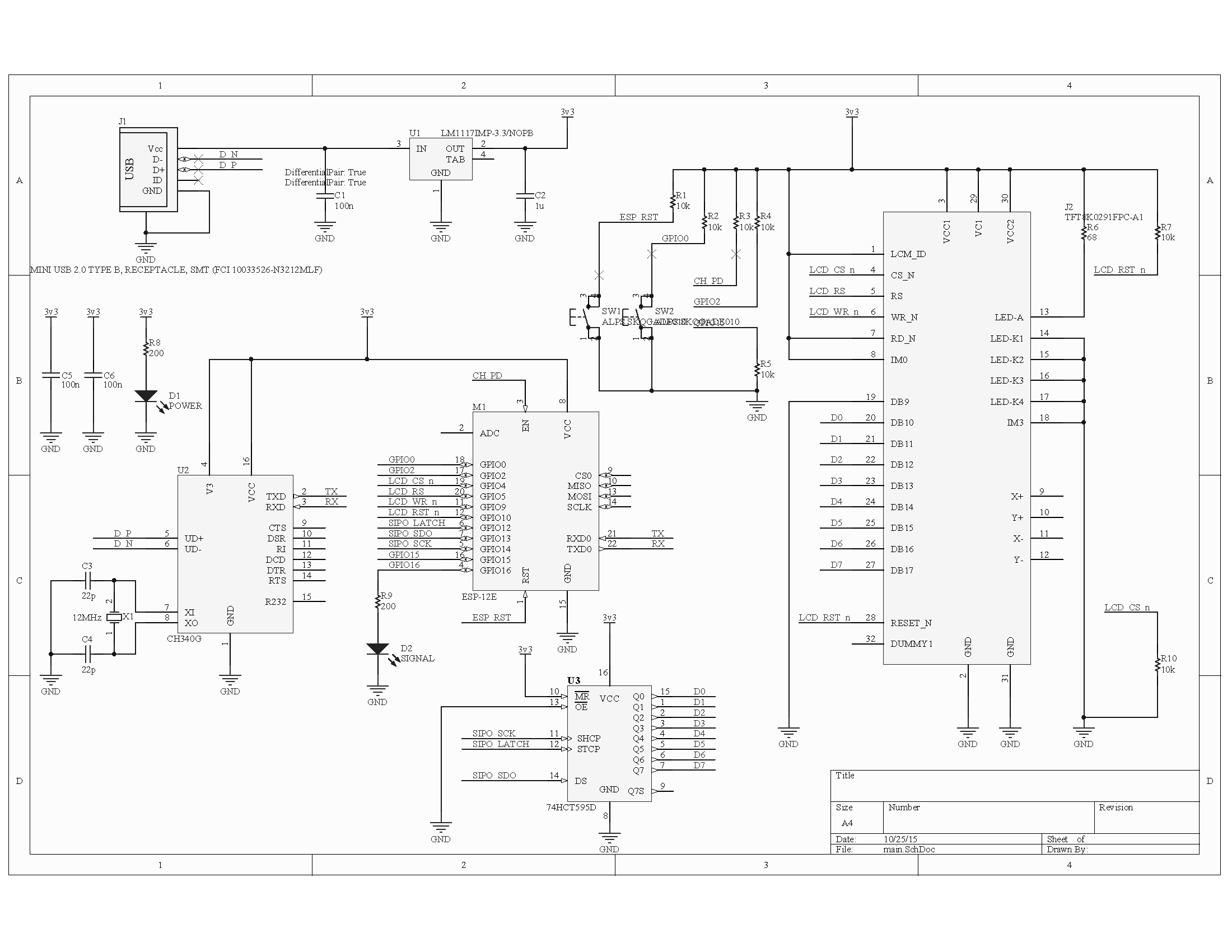
So here's the schematic I did for "Revision 1". That's the version that got made.
![]()
It's pretty simple. USB connector, linear 3.3v regulator, a cheap Chinese CH340G USB-UART bridge, ESP-12E module, and a serial-parallel shift register.
The UART bridge programs the ESP8266, the shift register is to handle the parallel inputs of the LCD module itself.
There are definitely some things I don't like about it already, but that's what a prototype is for!
I'll detail some of them in the next log.
 Jarrett