I have been doing this project for quite a long time and this is the third and final major revision of the project.
Server
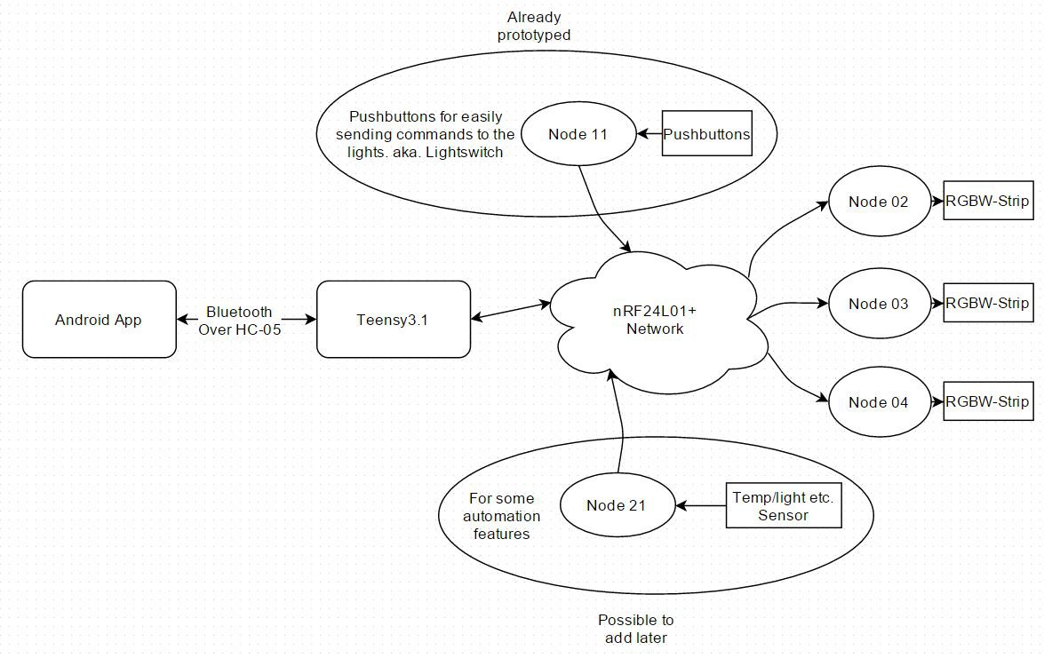
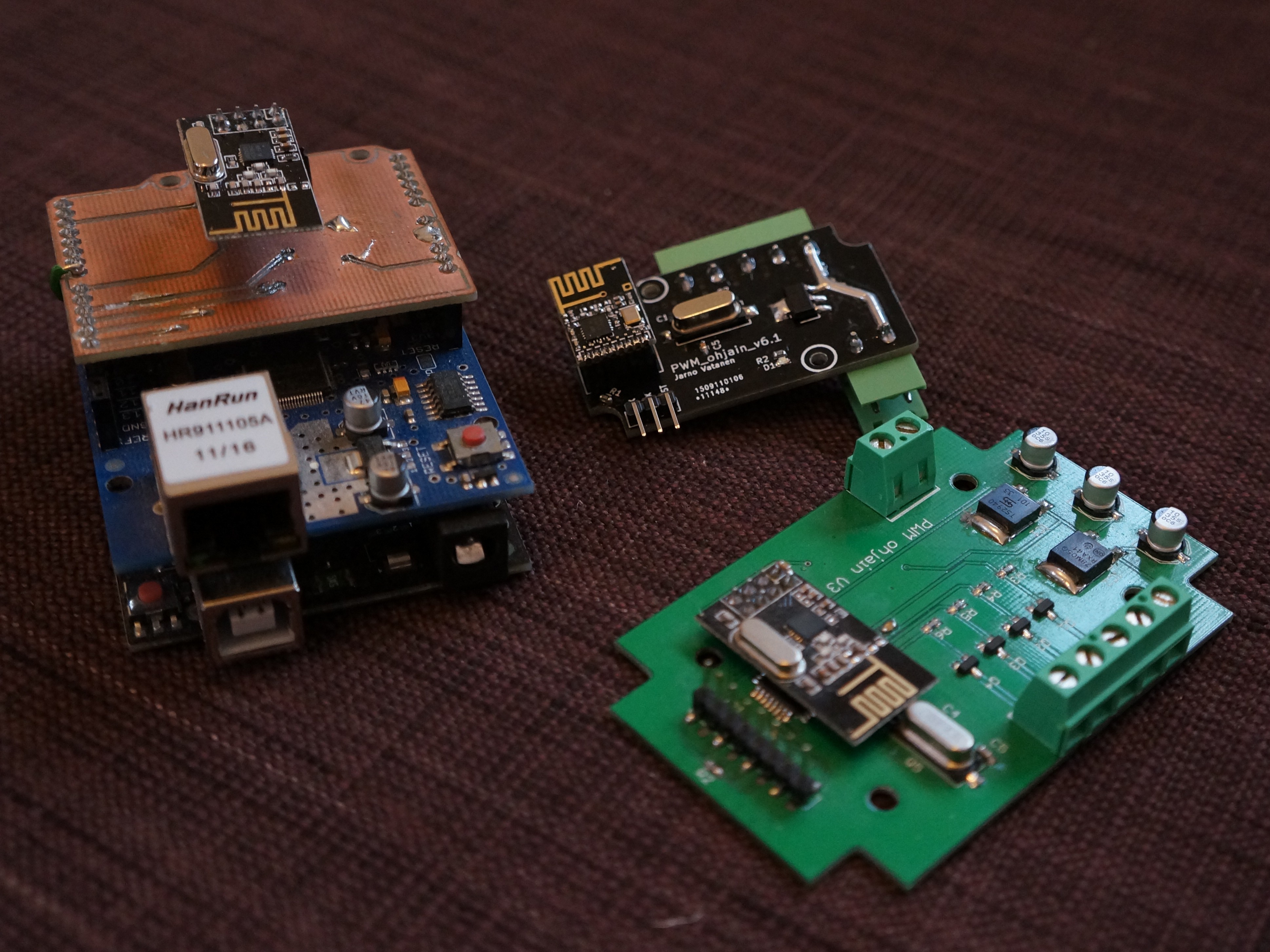
The server or the data transmitter consists of a RPi 3 with bluetooth and an nRF24L01+ radio module. (433MHz radio module coming also). Old version used a Teensy and a bluetooth module.
Receiver
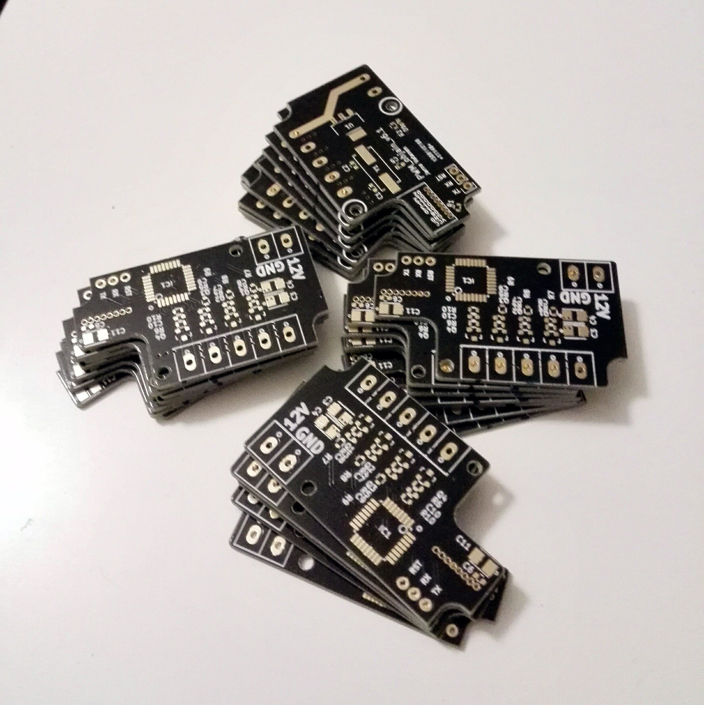
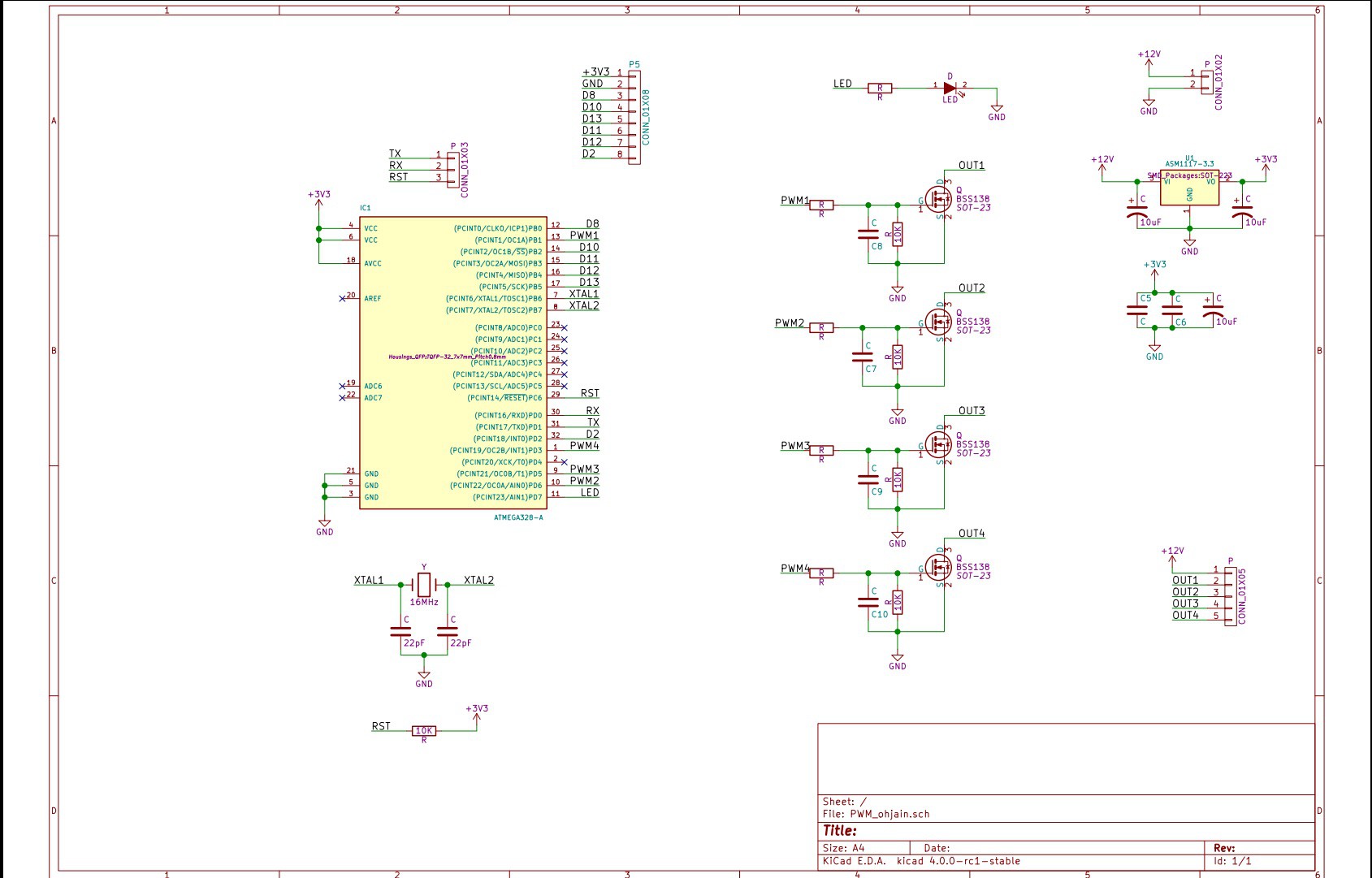
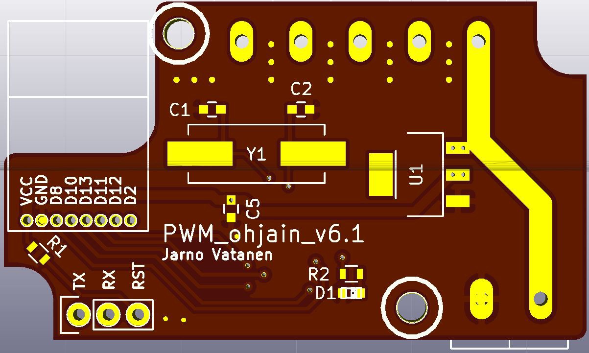
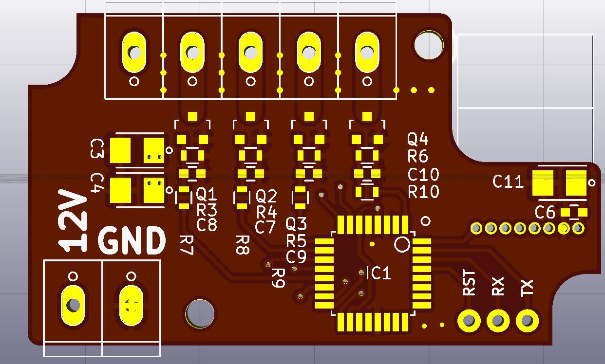
The receiver is a custom PCB with a Atmega328P chip, 4 MOSFETS and an nRF24L01+ radio module. It can control an RGBW LED strip.
Controller
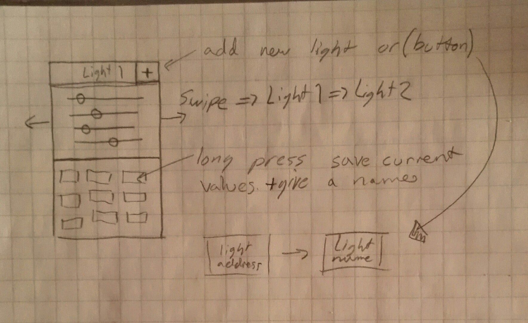
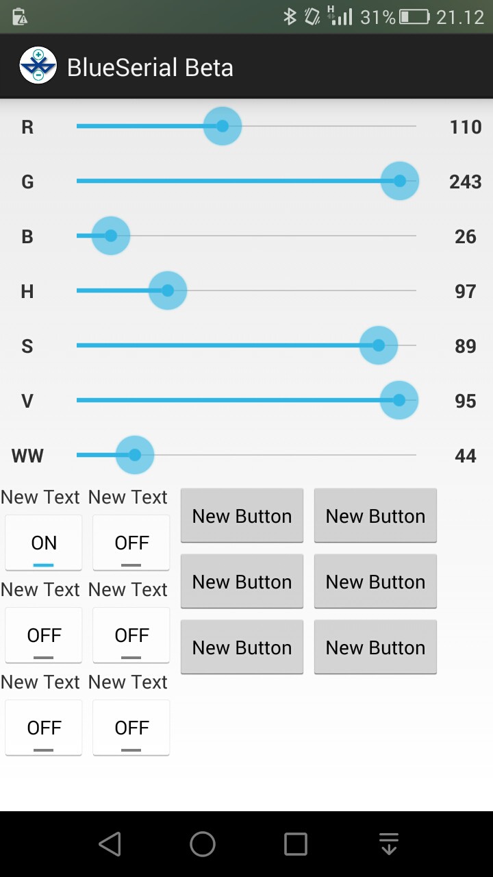
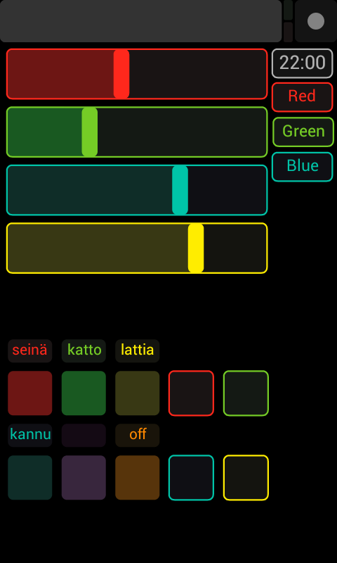
For sending commands to the server I use an Android phone. The App is still in it's early phase, but it's usable in a everyday usage. It's also possible to send commands without a phone with a "lightswitch" circuit. This way you can quickly turn off/on the lights with the separate circuit or fine tune the color through the phone App.
A working demo of the App.
 joedefa
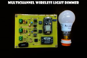
 H00GiE