 zakqwy
So, remote control time. I could have bought one off the shelf that does the exact same thing but that is dumb and I like soldering.
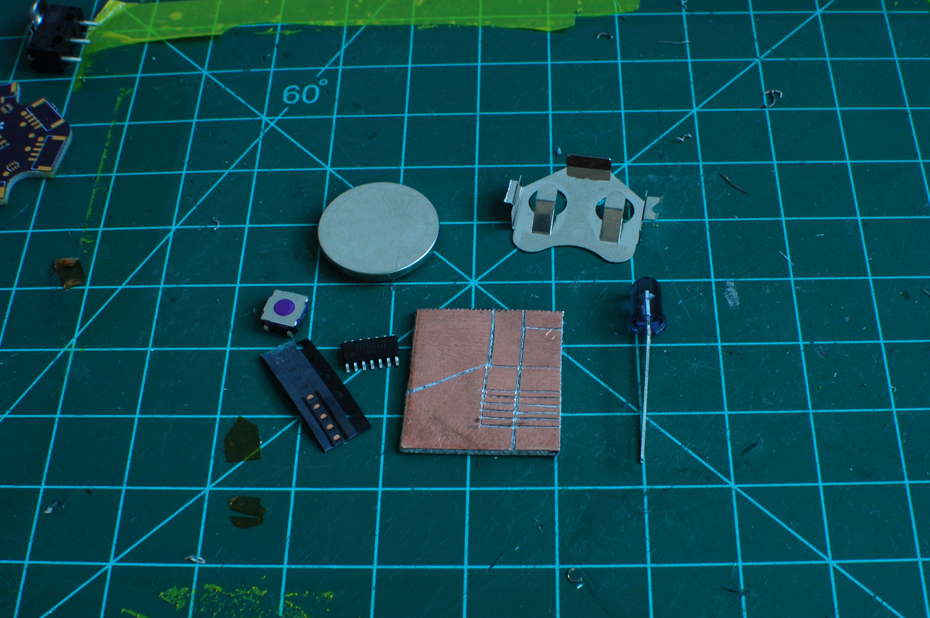
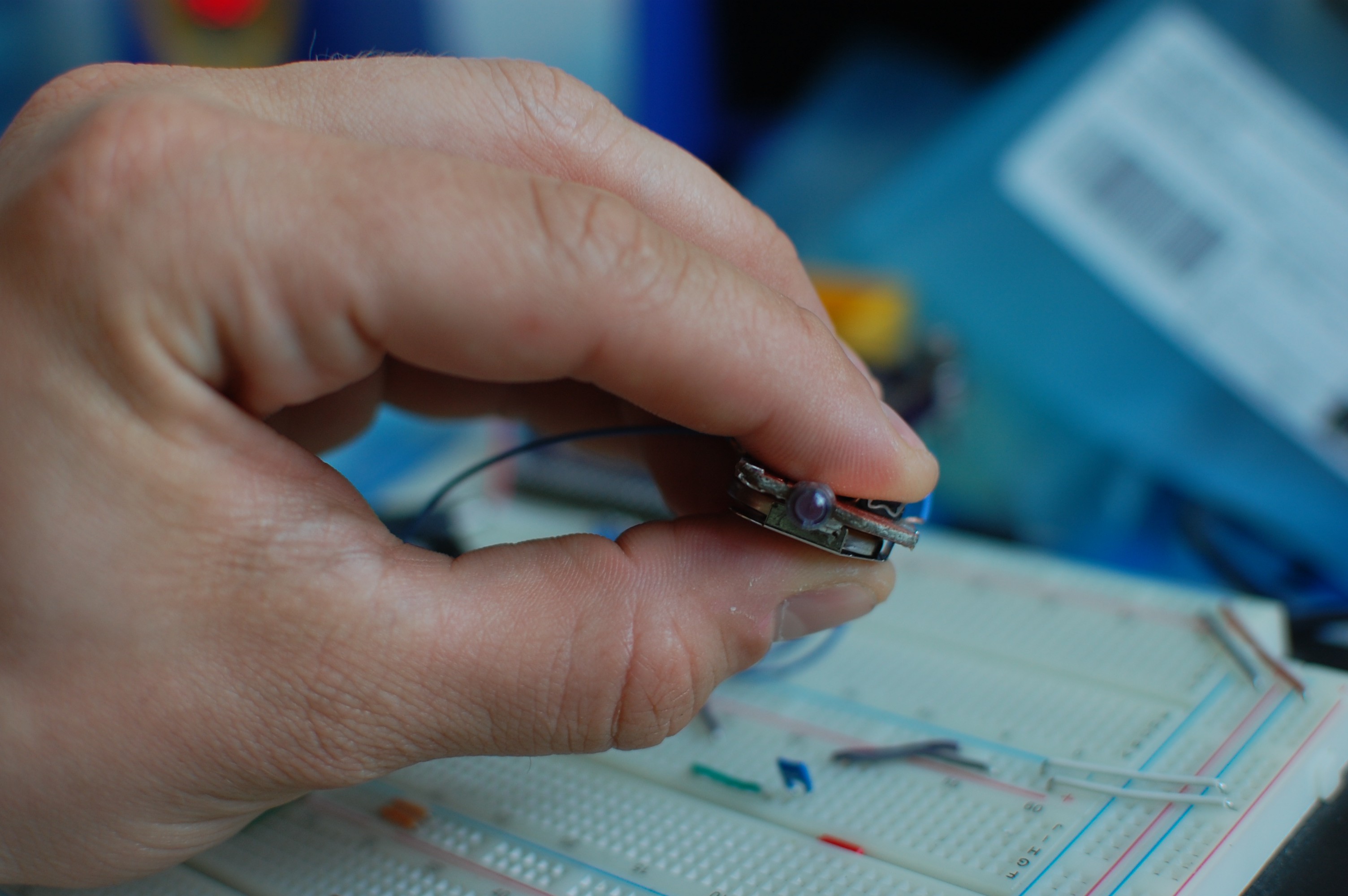
Not much to it. ATtiny44 (left over from #NeuroBytes v0.4), a high-output IR LED, a tiny pink indicator LED (extra from #blinktronicator), a pushbutton switch, a CR2032 battery and holder, and a carved up chunk of FR4. Not shown: current limiting resistors for the LEDs and a bypass cap for the microcontroller.
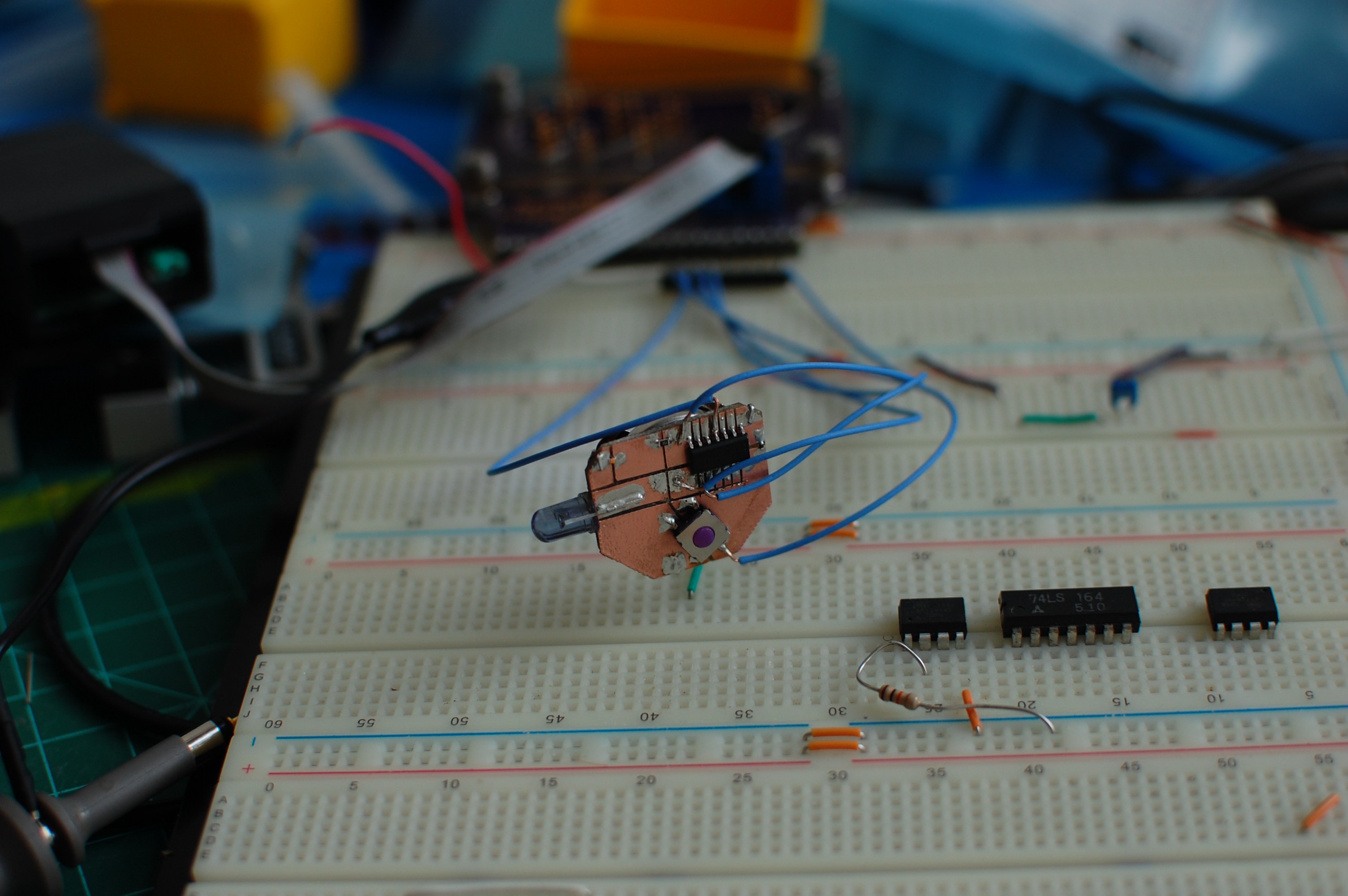
Programming connectors were tacked on during hasty firmware development. I re-used the #NeuroBytes v0.9 programmer since it's already a bit outdated.
/*
Nikon Remote Control by Zach Fredin, June 2016
zachary.fredin@gmail.com

Released under the terms of the MIT License.

The MIT License (MIT)
Copyright (c) 2016 by Zach Fredin
Permission is hereby granted, free of charge, to any person obtaining a copy of this software and associated documentation files (the "Software"), to deal in the Software without restriction, including without limitation the rights to use, copy, modify, merge, publish, distribute, sublicense, and/or sell copies of the Software, and to permit persons to whom the Software is furnished to do so, subject to the following conditions:

The above copyright notice and this permission notice shall be included in all copies or substantial portions of the Software.

THE SOFTWARE IS PROVIDED "AS IS", WITHOUT WARRANTY OF ANY KIND, EXPRESS OR IMPLIED, INCLUDING BUT NOT LIMITED TO THE WARRANTIES OF MERCHANTABILITY, FITNESS FOR A PARTICULAR PURPOSE AND NONINFRINGEMENT. IN NO EVENT SHALL THE AUTHORS OR COPYRIGHT HOLDERS BE LIABLE FOR ANY CLAIM, DAMAGES OR OTHER LIABILITY, WHETHER IN AN ACTION OF CONTRACT, TORT OR OTHERWISE, ARISING FROM, OUT OF OR IN CONNECTION WITH THE SOFTWARE OR THE USE OR OTHER DEALINGS IN THE SOFTWARE.

Uses ATtiny44A microcontroller, because that's what I had on hand.
High-output IR LED connected to pin 8 (PA5/OC1B) and VCC; set low to illuminate.
Pink indicator PicoLED connected to pin 7 (PA6) and VCC; set low to illuminate.
Momentary switch supplies power to microcontroller, so it should immediately
execute code.

Nikon timing from https://learn.adafruit.com/ir-sensor/making-an-intervalometer

*/

#include <avr/io.h>
#include <avr/interrupt.h>

uint8_t step = 0; //current stage of IR waveform
uint8_t IRsig[2][18] = {
	{ 62,255,255,255, 78, 12, 47, 15,109, 15,255,255,255,255,255,255,255,158},
	{  1,  0,  0,  0,  0,  1,  0,  1,  0,  1,  0,  0,  0,  0,  0,  0,  0,  0}
};
uint8_t repeat = 0;


void SystemInit(void) {
	DDRA |= ((1<<PA5) | (1<<PA6));
	PORTA &= ~(1<<PA6); //leave pink LED on the whole time
	PORTA |= (1<<PA5); //turn off IR LED to start

	TIMSK0 |= (1<<OCIE0A); //enables Timer 0A output compare match interrupt
	TCCR0A |= (1<<WGM01); //CTC mode
	TCCR0B |= (1<<CS02); //prescales to clk/256 (31.25 kHz)
	OCR0A = 1;

	TCCR1A |= (1<<COM1B0); //toggle OC1B on compare match
	TCCR1B |= (1<<WGM12); //CTC mode
	OCR1A = 12;
	OCR1B = 12; //generates 38 kHz square wave on OC1B

	sei();
}

ISR(TIM0_COMPA_vect) {
	if (IRsig[1][step]) {
		TCCR1B |= (1<<CS11);
		TCCR1A |= (1<<COM1B0);
		TCCR1B |= (1<<WGM12);
	}
	else {
		TCCR1A = 0;
		TCCR1B = 0;
		PORTA |= (1<<PA5);
	}
	OCR0A = IRsig[0][step];
	step++;
	if (step == 18) {
		step = 0;
		repeat++;
		if (repeat == 2) {
			TCCR1A = 0;
			TCCR1B = 0;
			TCCR0A = 0;
			TCCR0B = 0;
			TIMSK0 = 0;
			cli();
		}
	}
}

int main(void) {
	SystemInit();
	for(;;) {

	}
}
I used both timers on the ATtiny44; since the IR LED is hooked up to PA5 (which is OC1B), I used Timer/Counter 1 to generate the 38 kHz square wave and the timer 0 interrupt to toggle said square wave on and off as appropriate, according to the IRsig[][] array. 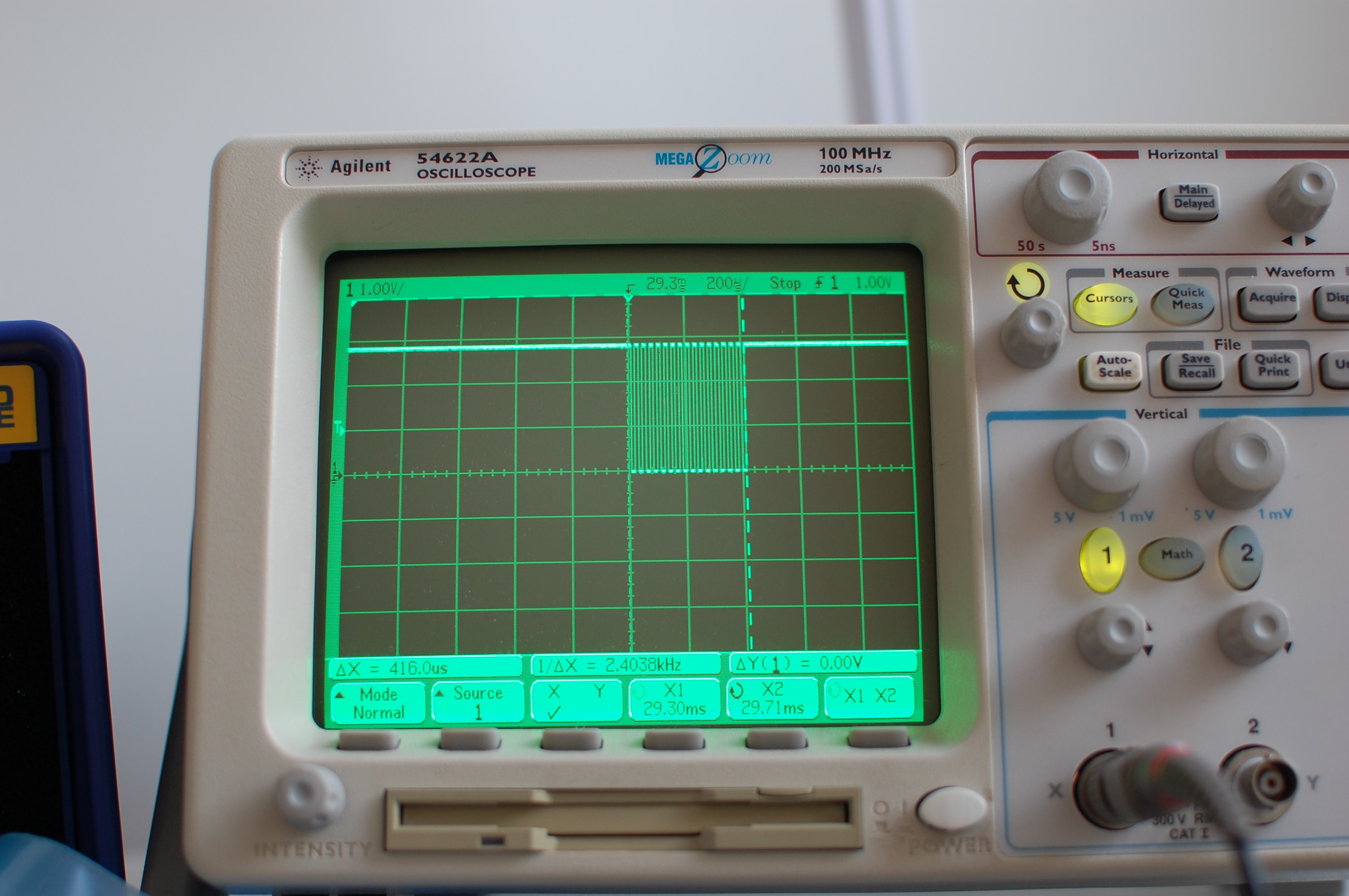
Close up of the 'scope trace for an individual 38 kHz pulse. I had to tweak OCR1x a bit to get the frequency right, which isn't surprising as I'm using the internal RC oscillator.
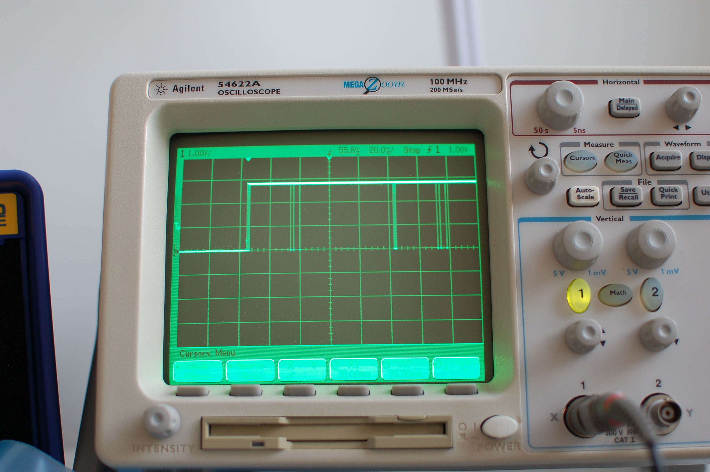
The complete [double] signal; as you can see in the code, after firing the pulses twice the repeat counter shuts off both timers and disables interrupts to be sure. Yes, all the switch does is turn power on to the board; the microcontroller starts up fast enough that it's fine for my purposes, and avoids the need to deal with stuff like sleep mode to save battery life.
Obligatory first picture taken using the remote! Worked like a charm.

My office is ~40' long and I wasn't quite up against the wall, so call it a 35' range. This picture turned out at bit funky because my windows face west and the sun was setting.
If you want to build your own, I found Nikon timing specs in a number of places including @limor's intervalometer write-up. She takes the project a step further by building a full timer platform for taking time lapse photos--definitely a worthwhile add-on for a future DIY Nikon remote!
Discussions
Become a Hackaday.io Member
Create an account to leave a comment. Already have an account? Log In.
Oh, I so need to build one of these. I know I have some tiny44's kicking around and the IR LEDs too. Does this work for auto-focus and video too? Nice work on tweaking for oscillator variance.
Are you sure? yes | no
Just the remote shutter. Good o'l D40 doesn't do fancy things like 'video', and as far as I can tell it doesn't do remote auto-focus either. Definitely a solid rainy Sunday project. Let me know if you need a pink LED, I've got a few extra and it makes the remote Kick Ass.
Are you sure? yes | no
A friend asked about doing the same thing, but for a Canon. A bit of quick searching turned up this: http://www.doc-diy.net/photo/rc-1_hacked/
The Canon protocol is a bit simpler; the IRsig lookup array in my code could be replaced with a simple counter function that toggles the ISR at a fixed pace. Would keep the ISR much shorter which I hear is good practice anyway. Otherwise, the hardware should work the same.
Are you sure? yes | no