 zakqwy
Or 'Twist Wrist', or 'persistence-of-vision arm clock', or something like that. This project doesn't technically fall into the #weekend novelty projects category, mostly because I worked on it for slightly more than a weekend (with a large gap in the middle). However, I'm not likely to take it much further, so here the documentation will remain. Everything is released under the MIT License, and the pertinent files are stored in the project page's file repository.
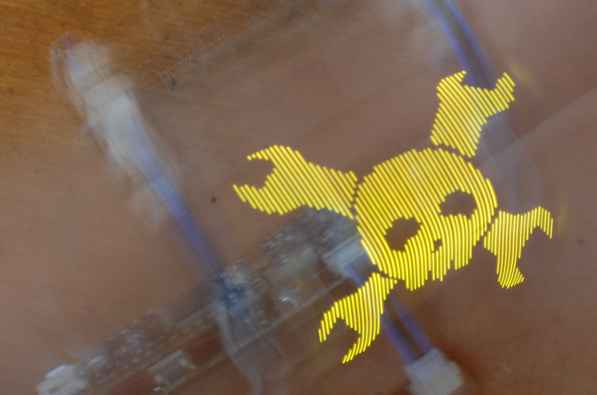
Yes, as the picture above suggests: this project is actually Pretty Damn Cool, although for now (and likely for a long time) it only works in 'Hackaday pandering mode'. I haven't had a chance to put together a proper font library or any of the time setting functions, and I really need to run the accelerometer in interrupt mode to improve the repeatability of the image generation. Someday I hope it will display the current time when prompted.
Hardware
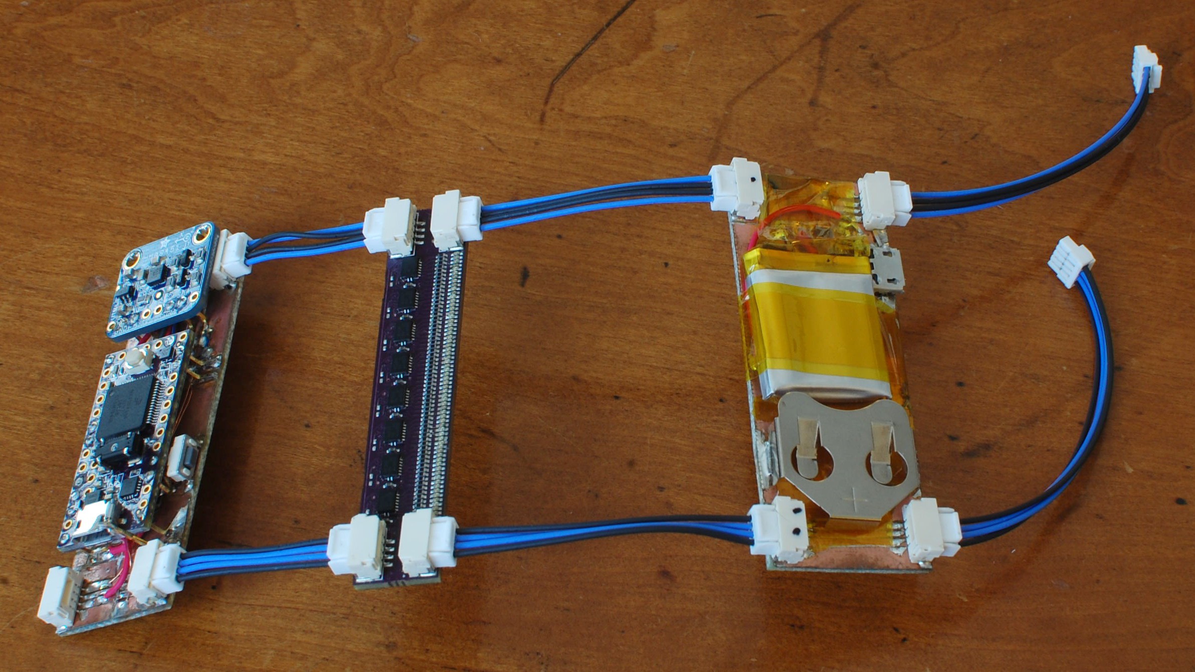
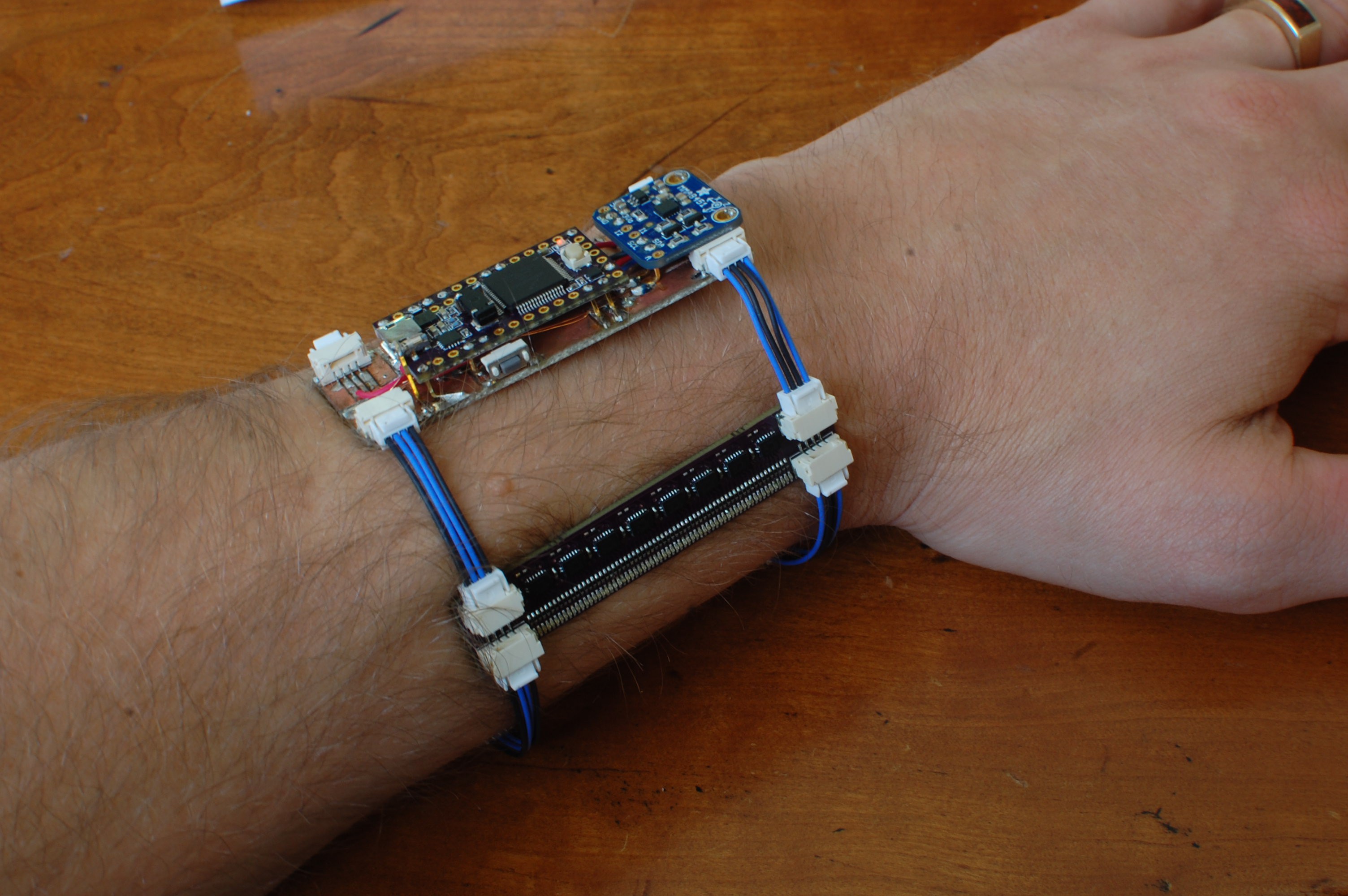
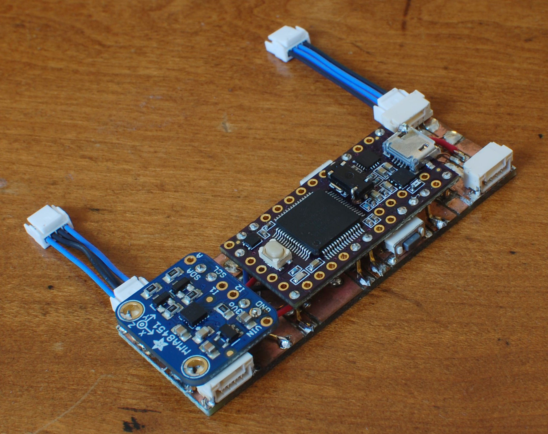
The project consists of three boards shown above left to right: a processor / accelerometer board, a display board, and a LiPo battery / backup battery / charging circuit board. The boards are linked together using JST GH jumpers (since I have the tool to make the crimp terminals), carefully sized to accommodate my left wrist:
Processor Board
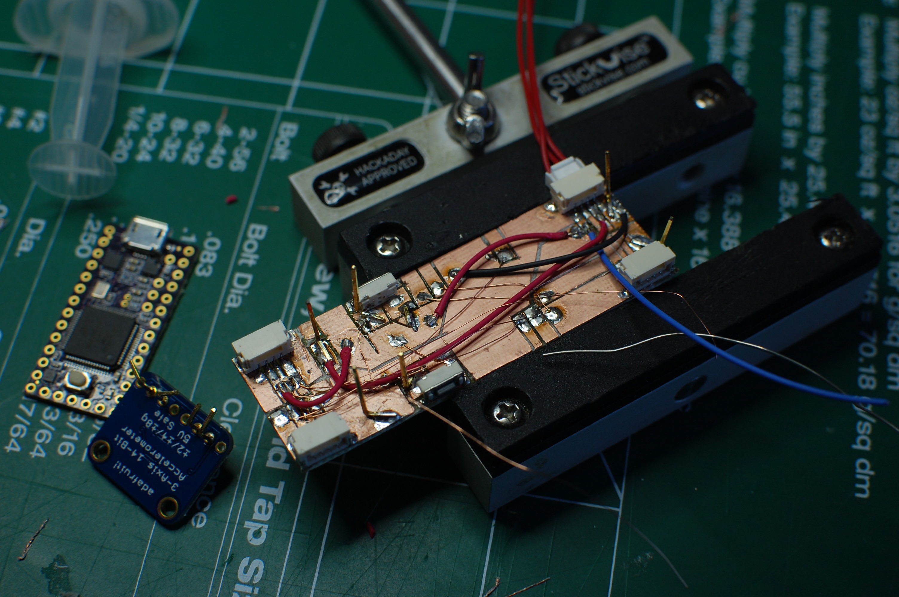
The processor board, shown above during assembly, consists of a small piece of FR4 with JST GH headers at each corner, along with interconnected mounting pads intended to mate up to specific pins on the Teensy v3.2 and Adafruit accelerometer breakout board. These two components are supported using trimmed bits of right angle header.
| Component | Qty |
| Teensy 3.2 without headers (OSHpark edition optional) | 1 |
| Adafruit MMA8451 accelerometer breakout board | 1 |
| 32.768 kHz 12.5 pF SMD crystal | 1 |
| FR4, 1/16", 1oz copper (single sided) | 22x67 mm |
| JST GH Headers, 4-position, side entry | 4 |
| SPST Swtich, right angle SMD, E-Switch p/n TL3330AF130QG | 2 |
| 26 AWG stranded wire, insulated | 30 cm |
| 34 AWG solid copper wire, enameled | 20 cm |
| 10k resistor, 0402 | 2 |
| Header pins, right angle, trimmed as needed | ~20 |
Once everything is soldered down and trimmed the board is quite a bit more compact, and all the wiring is somewhat protected underneath:
Power Board
Let me start by suggesting that this board is a bit sketchy. I insulated the battery leads fairly thoroughly and used quite a bit of care and clearance with the solder joints, but I still recommend against duplicating it unless you know what you are doing.
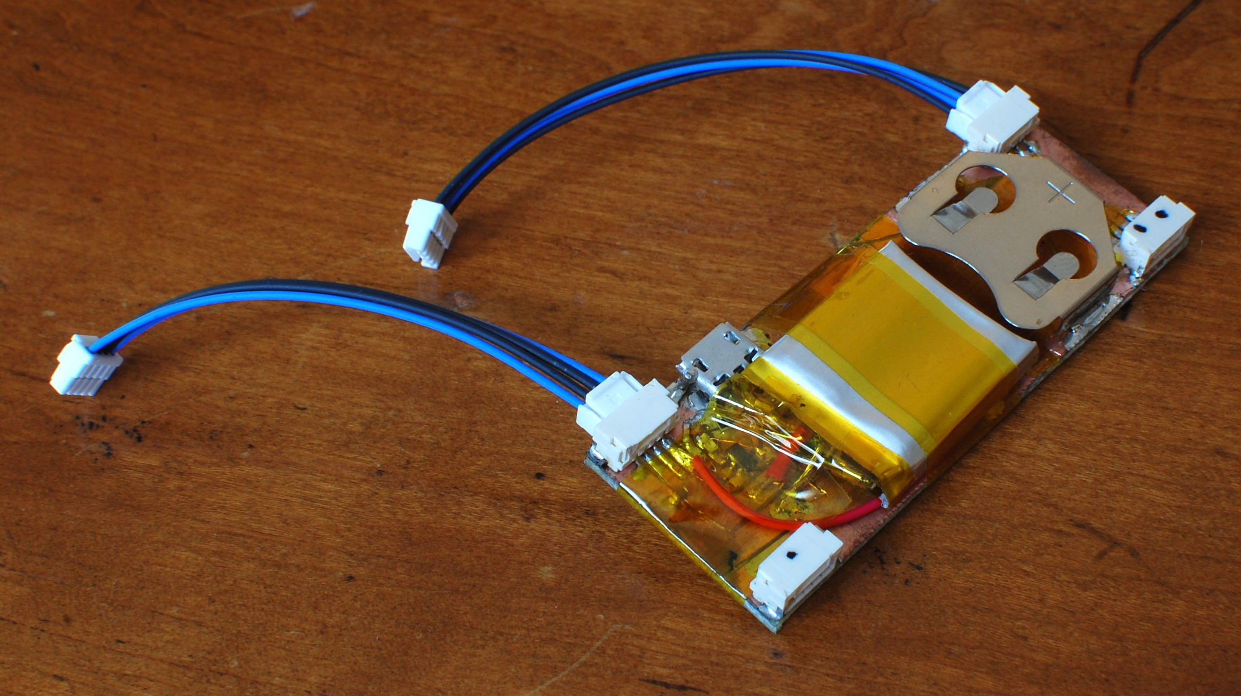
The power board consists of two supplies: a 3v 2032 lithium coin cell and a 1S 150mA LiPo cell with an accompanying charge circuit and uUSB plug. The coin cell was originally intended to power the Teensy's battery backup circuit, but I think I wired the grounds up wrong and it didn't work properly (hence the lack of battery in the clip). The rechargable side is essentially the reference circuit from the Microchip MCP73831 datasheet, tweaked to provide a 100mA charging rate. As such, the BOM is as follows:
| Component | Qty |
| LiPo battery with protection circuit, 150mA, 1S | 1 |
| CR2032 coin cell clip, SMD, with trimmed 'wings' | 1 |
| Micro-USB plug, SMD | 1 |
| FR4, 1/16", 1oz copper (single sided) | 25x67 mm |
| JST GH Headers, 4-position, side entry | 4 |
| 26 AWG wire, insulated | 10 cm |
| 0603 LED, 650nm | 1 |
| 4.7 uF ceramic capacitors, 10vdc | 2 |
| 330 ohm resistor, 0603 | 1 |
| 10k resistor, 0603 (replaces 2k resistor in reference circuit) | 1 |
| Kapton tape | 10 cm |
Again--a bit sketchy, because LiPo batteries can be dangerous if accidentally shorted or otherwise damaged. My battery does include a built-in protection circuit and the charging bits are solid, but the construction method means it is still vulnerable.
Display Board
This part kinda disqualifies the project from falling under the 'weekend novelty projects' category since I designed and built it a number of months ago; however, given the single-log nature of this build I'm still including it here.
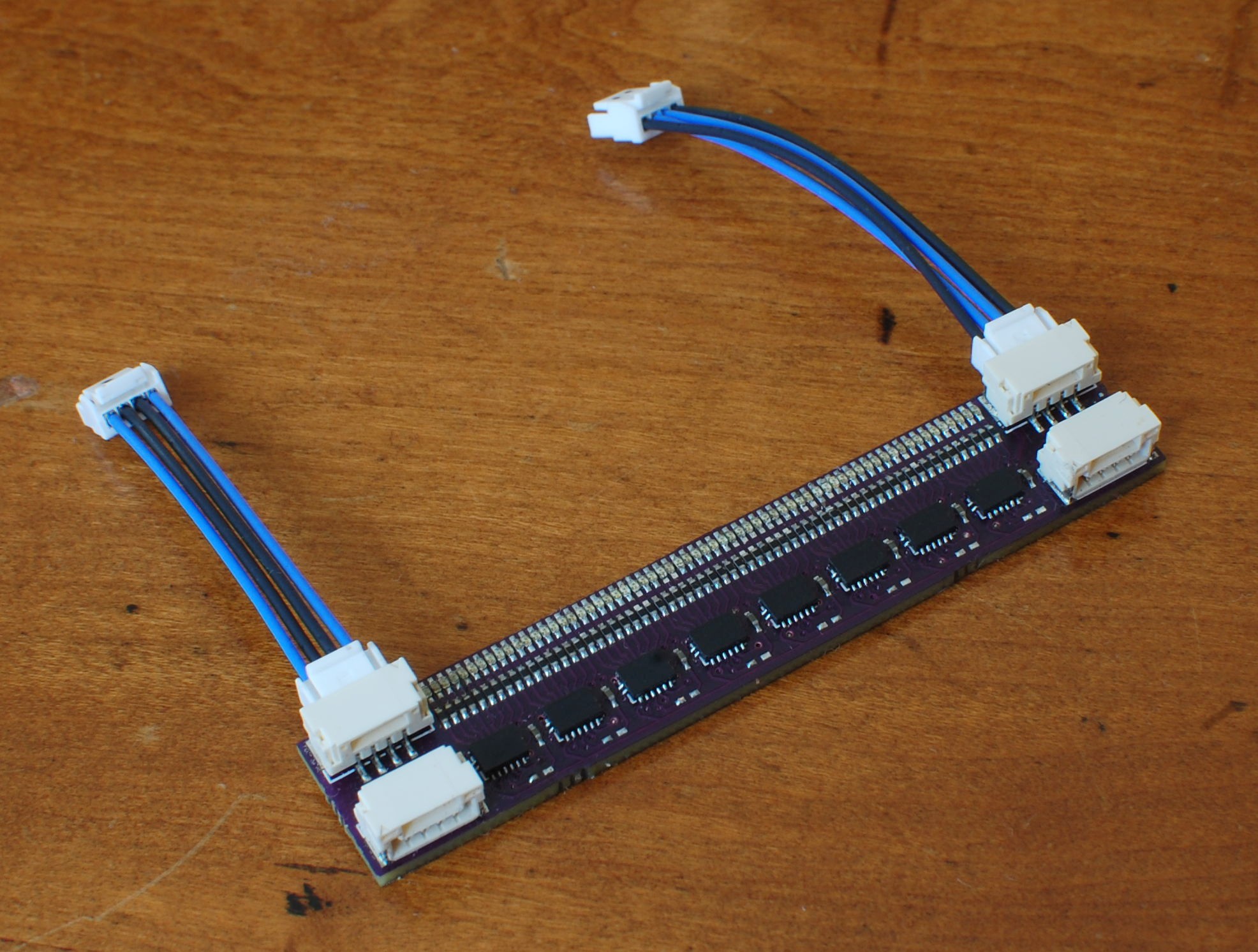 This board consists of 64 yellow LEDs, 64 current limiting resistors, and eight HC595 shift registers arranged sequentially. In addition to the data, SRCLK, and RCLK lines, I've broken out the master reset and output enable lines for some reason. Experimentation?
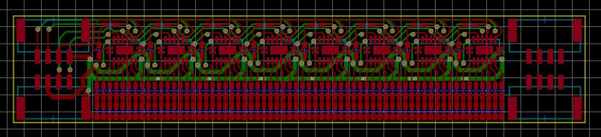 The PCB was thoroughly enjoyable to route, and was actually the first part of the project; I wanted to continue working with the 0402 LEDs and itty bitty (2.5x3.5 mm!) HC595s I discovered with #blinktronicator. A larger persistence-of-vision array seemed like a logical step, and the watch concept followed later. I tried using resistor arrays but had trouble squeezing them in; the LEDs and discrete resistors are laid out on 0.75mm centers, which is a decent bit below the manufacturer's recommendation.
| Component | Qty |
| NXP 74HC595, DHVQFN-16 package | 8 |
| Rohm PicoLEDs, 580nm | 64 |
| 59 ohm resistor, 0402, 1% | 64 |
| 0.1 uF capacitor, 0402 | 8 |
| PCB, probably not homemade (due to pin pitch requirements) | 12x67 mm |
| JST GH Headers, 4-position, side entry | 4 |
The full schematic and PCB layout files (both Gerber and KiCAD) will be added to this project's file repository. They also include another board (one that integrates the power supply with a gyroscope and an ATmega328) but this board has a few issues--so don't try building it. Finally, note that at full brightness the LEDs do draw a fair bit more current than the HC595s would prefer. They heat up a bit but haven't failed yet; just know that they're getting pushed fairly far past their design guidelines (uh, 70 mA vs 160 mA). Note that this could be solved using higher efficiency LEDs, but you'd probably have to give up that sweet 580nm yellow.
One last note: I do recommend using a stencil and reflowing this board rather than attempting it by hand. The HC595 doesn't require its thermal pad to be connected electrically, but it does help a great deal thermally and is worthwhile in this scenario. I used a Kapton stencil from OSH Stencils and ended up having to hand-rework half the LED array, but it still saved a lot of time.
Firmware
The Arduino code runs on a Teensy v3.2 and is included in the file repository for this project page. I used the method suggested by Mike and others for driving the LED array: SPI! That made the wiring and code both relatively simple once the basic commands were sorted out.
/*
 * TwistWrist v2
 * copyright 2016 by Zach Fredin
 * zachary.fredin@gmail.com
 *
 * v2, because the v1 control board (which was an actual pcb) had
 * some issues. v2 is carved up fr4.
 *
 */

#include <SPI.h>
#include <Adafruit_MMA8451.h>
#include <Adafruit_Sensor.h>
#include <Wire.h>

#define DISP_SCLK 13
#define DISP_DATA 11
#define DISP_RCK 10
#define DISP_MR 3
#define DISP_OE 22
#define PB_TOP 23
#define PB_BOT 2

uint8_t imgJR[59][8] = {
  {0x03,0xe0,0x00,0x00,0x00,0x00,0x03,0x80},
  {0x01,0xf8,0x00,0x00,0x00,0x00,0x1f,0xc0},
  {0x00,0xfc,0x00,0x00,0x00,0x00,0x3f,0x00},
  {0x00,0x7e,0x00,0x00,0x00,0x00,0x7e,0x00},
  {0x00,0x3e,0x00,0x00,0x00,0x00,0x7c,0x00},
  {0x00,0x3f,0x00,0x00,0x00,0x00,0xfc,0x00},
  {0x00,0x7f,0x00,0x00,0x00,0x00,0xfc,0x00},
  {0x80,0xff,0x00,0x00,0x00,0x00,0xfe,0x01},
  {0xe1,0xff,0x80,0x00,0x00,0x00,0xff,0x87},
  {0xf3,0xff,0xc0,0x00,0x00,0x01,0xff,0xcf},
  {0xff,0xff,0xe0,0x00,0x00,0x03,0xff,0xff},
  {0x7f,0xff,0xf0,0x00,0x00,0x07,0xff,0xfe},
  {0x3f,0xff,0xf8,0x00,0x00,0x0f,0xff,0xfe},
  {0x3f,0xff,0xfc,0x00,0x00,0x1f,0xff,0xfc},
  {0x0f,0xff,0xfe,0x00,0x00,0x7f,0xff,0xf8},
  {0x00,0x3f,0xfe,0x1f,0xf8,0x7f,0xff,0xe0},
  {0x00,0x0f,0xf8,0xff,0xff,0x3f,0xf8,0x00},
  {0x00,0x07,0xf3,0xff,0xff,0xdf,0xf0,0x00},
  {0x00,0x03,0xe7,0xff,0xff,0xef,0xc0,0x00},
  {0x00,0x01,0xef,0xff,0xff,0xf7,0x80,0x00},
  {0x00,0x00,0xdf,0xff,0xff,0xfb,0x00,0x00},
  {0x00,0x00,0x1f,0xff,0xff,0xfa,0x00,0x00},
  {0x00,0x00,0x3f,0xff,0xff,0xfc,0x00,0x00},
  {0x00,0x00,0x3f,0xff,0xff,0xfc,0x00,0x00},
  {0x00,0x00,0x7f,0xff,0xff,0xfe,0x00,0x00},
  {0x00,0x00,0x7f,0xff,0xff,0xfe,0x00,0x00},
  {0x00,0x00,0x7e,0x1f,0xf8,0xfe,0x00,0x00},
  {0x00,0x00,0xfc,0x07,0xe0,0x3f,0x00,0x00},
  {0x00,0x00,0xf8,0x07,0xe0,0x1f,0x00,0x00},
  {0x00,0x00,0xf8,0x03,0xc0,0x1f,0x00,0x00},
  {0x00,0x00,0xf8,0x07,0xe0,0x1f,0x00,0x00},
  {0x00,0x00,0xf8,0x1f,0xf0,0x1f,0x00,0x00},
  {0x00,0x00,0xf8,0x7f,0xfe,0x1f,0x00,0x00},
  {0x00,0x00,0xfc,0xff,0xff,0x3f,0x00,0x00},
  {0x00,0x00,0xfe,0xff,0xff,0x7e,0x00,0x00},
  {0x00,0x00,0x7f,0xff,0xff,0xfe,0x00,0x00},
  {0x00,0x00,0x7f,0xfe,0x7f,0xfe,0x00,0x00},
  {0x00,0x01,0x3f,0xfe,0x7f,0xfc,0x80,0x00},
  {0x00,0x03,0x3f,0xfe,0x7f,0xfd,0xc0,0x00},
  {0x00,0x07,0x9f,0xff,0x3f,0xf9,0xe0,0x00},
  {0x00,0x0f,0xdf,0xff,0xff,0xfb,0xf8,0x00},
  {0x00,0x3f,0xcf,0xff,0xff,0xf7,0xff,0xe0},
  {0x0f,0xff,0xe7,0xff,0xff,0xef,0xff,0xf0},
  {0x1f,0xff,0xf3,0xff,0xff,0xdf,0xff,0xfc},
  {0x3f,0xff,0xf1,0xff,0xff,0x8f,0xff,0xfc},
  {0x7f,0xff,0xf1,0xf7,0xdf,0x87,0xff,0xfe},
  {0x7f,0xff,0xe1,0xf7,0xdf,0x83,0xff,0xde},
  {0xf3,0xff,0xc0,0xf3,0xcf,0x01,0xff,0x8f},
  {0xe1,0xff,0x80,0x01,0x00,0x01,0xff,0x87},
  {0xc0,0xff,0x00,0x00,0x00,0x01,0xff,0x03},
  {0x80,0x7f,0x00,0x00,0x00,0x00,0xfe,0x00},
  {0x00,0x7f,0x00,0x00,0x00,0x00,0xfc,0x00},
  {0x00,0x3f,0x00,0x00,0x00,0x00,0xf8,0x00},
  {0x00,0x3e,0x00,0x00,0x00,0x00,0xfc,0x00},
  {0x00,0x7e,0x00,0x00,0x00,0x00,0x7e,0x00},
  {0x00,0xfc,0x00,0x00,0x00,0x00,0x3f,0x00},
  {0x01,0xf8,0x00,0x00,0x00,0x00,0x1f,0x80},
  {0x03,0xe0,0x00,0x00,0x00,0x00,0x03,0x80},
};

Adafruit_MMA8451 mma = Adafruit_MMA8451();
uint8_t accelArmed = 0; //flip to 1 when accel detects initial arm rotation
uint8_t dispBuffer[8] = {0,0,0,0,0,0,0,0};
uint32_t armCount = 0;
uint32_t armReset = 1000;
uint8_t jrCount = 0;
uint8_t startDisp = 0;

void setup() {
  pinMode(PB_TOP, INPUT);
  pinMode(PB_BOT, INPUT);
  pinMode(DISP_RCK, OUTPUT);
  pinMode(DISP_OE, OUTPUT);
  pinMode(DISP_MR, OUTPUT);
  SPI.begin();
  digitalWrite(DISP_OE, LOW);
  digitalWrite(DISP_MR, HIGH);

  mma.begin();
  mma.setRange(MMA8451_RANGE_8_G);
  Serial.begin(115200);
}

void isArmed() {
  mma.read();
  Serial.println(mma.x);
  if (mma.x > 3500) {
    accelArmed = 1;
    armCount = armReset;
  }
}

void writeDisp() {
  uint8_t i = 0;
  digitalWrite(DISP_RCK, LOW);
  for (i=0;i<8;i++) {
    SPI.transfer(dispBuffer[i]);
  }
  digitalWrite(DISP_RCK, HIGH);
}

void blankDisp() {
  uint8_t i = 0;
  for (i=0;i<8;i++) {
    dispBuffer[i] = 0;
  }
}

void dispJR() {
  uint8_t j = 0;
  for (j=0;j<8;j++) {
    dispBuffer[j] = imgJR[jrCount][j];
  }
  jrCount--;
  if (jrCount == 0) {
    jrCount = 58;
    startDisp = 0;
  }
}

void loop() {
  isArmed();
  if (accelArmed == 1) {
    mma.read();
    Serial.println(mma.x);
    armCount -= 1;
    if (mma.x < -1500) {
      startDisp = 1;
      accelArmed = 0;
    }
  }
  else {
    blankDisp();
  }

  if (startDisp == 1) {
    dispJR();
  }

  if (armCount == 0) {
    accelArmed = 0;
  }
  writeDisp();
}
As you can imagine, the monster array is the Hackaday logo as a 64 bit wide black-and-white bitmap, broken into an uint8_t array. I used this website to generate the actual hex values after tweaking the Jolly Wrencher image to size. Otherwise, the Adafruit accelerometer driver library and the SPI library take care of most things. As I mentioned previously, pins can be identified from the #define section. To Do
... on this project, if I ever pick it up again:
- Get the numerical library and time functions working in firmware, so it's actually a watch.
- Figure out the battery backup issue so it doesn't have to stay charged all the time.
- Re-design the controller PCB, maybe to integrate with the power PCB as with the original design.
- Do something about the pinchy/sweaty arm issue. Maybe a sewn case of some kind.
- Wire up the accelerometer interrupt lines and figure out how it works, so the motion triggering is more repeatable (right now it takes a lot of flailing to get the display to light up at the right time).
Discussions
Become a Hackaday.io Member
Create an account to leave a comment. Already have an account? Log In.