Here is a more detailed render of two stages of a disc pump:
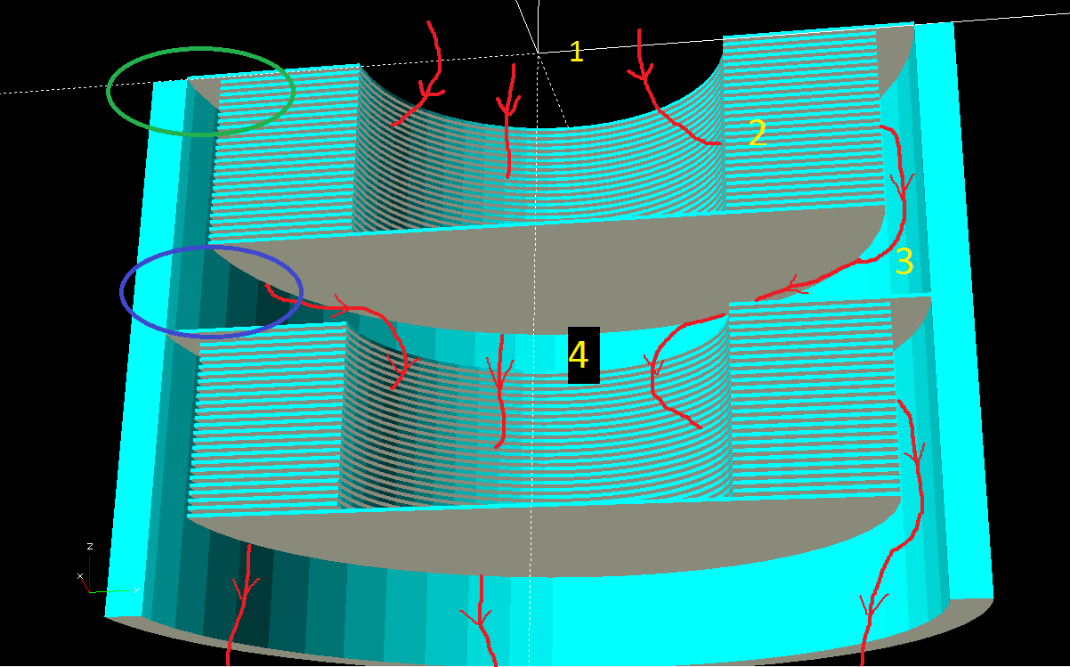
Red lines are hypothetical air streams, minus lots of spiraling for simplicity.
1. Air enters from the vacuum chamber
2. Passes into the thin gap in the discs, where it get accelerated rapidly and flung towards the outside
3. Air exits the discs at hopefully somewhat higher pressure, and follows along the stationary wall, where it begins slowing down.
4. Once it has lost enough energy the air makes it's way to the center intake hole of the next pump stage.
Two problem areas I foresee:
Green oval: The seal between the intake disc and the wall. This disc is the main barrier between the different stage pressures. Considering this disc is also rotating at high speed, I have no idea if it is even possible to make that be a halfway decent seal. Also, this intake disc must be a slightly larger radius than the other discs, making it more susceptible to hoop stresses and explosion. Basically, the rotational speed will be limited by this disc, but the compression limited by the smaller discs. Perhaps the disc-wall gap could be gradually varied, increasing from top to bottom?
Purple oval: Here the air has been given high kinetic energy (speed) from the discs, but must convert that into pressure before it can slow down and enter the central hole in the next stage. In normal centrifugal pumps this is done by the "diffuser", basically a finely tuned set of stator blades that slow the air down again. I had hoped to avoid the construction of blades due to their complexity, relying on friction with the outer wall to slow down the air. I have no idea how well this will work however. It could work fine, or the air might generate a bunch of heat from the friction. I understand that different diffuser design can do this "kinetic energy to pressure energy" conversion with various efficiencies, and I'm guessing the inefficient ones generate more heat and less pressure? But this is just my very uninformed reading of the Wikipedia page on centrifugal compressors. Any aerospace engineers reading this that might have some ideas? Do you think I'll need some kind of stator vanes in between stages?
I have one more design idea for a single stage version that would avoid all of these issues, that'll have to be tomorrow's write up.
Discussions
Become a Hackaday.io Member
Create an account to leave a comment. Already have an account? Log In.
Why not just make the wider disc (green oval) part of the stator? That would solve the sealing issue, I think. And that would be more similar to the previous render AIUI.
Are you sure? yes | no
It would! That's a great suggestion. To be honest, it's been so long since I made this render that I don't remember why I thought the big disc needed to spin. I think I was going for simplicity of construction. It looks simple enough with just two stages, but imagine a tube 15 stages long, 5+ feet. Either the stator discs have to be placed inside and sealed (picture reaching 3 feet inside a tube and soldering a good seal around the rotor with one hand) or the whole outer tube is assembled in 15 sections, leaving 15 more opportunities for leaks to atmospheric pressure. Having the big discs spin means the whole column of discs can be assembled on the axle first, then simply inserted into an intact tube. As far as I understand the original Tesla design this is how he constructed it as well. Of course that doesn't mean that's the best way to do it! Making the big discs stationary certainly solves a lot of issues, I'll have to think about how that could be assembled easily and consistently. Thanks for the idea!
Are you sure? yes | no