 Aleksander Kawęczyński
Schematic:
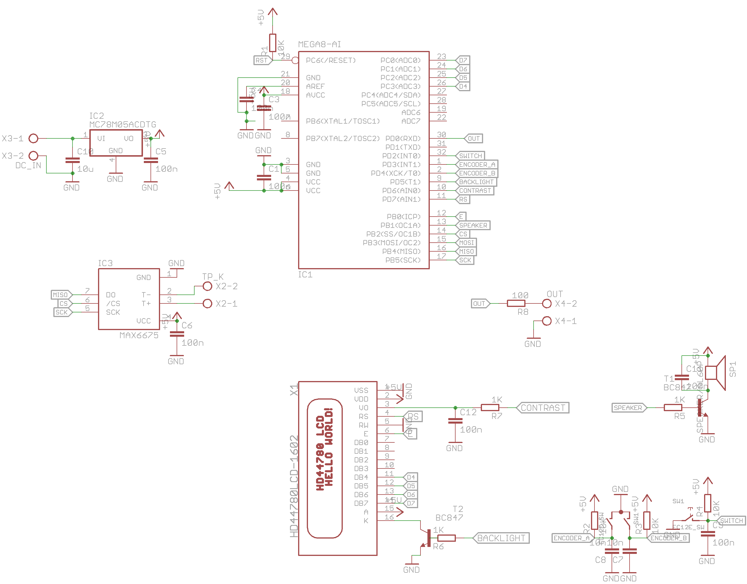
Atmega88 controls backlight and contrast of the LCD by software and PWM outputs. It works pretty well - the values will be stored in EEPROM. In my case good value for contrast is 50 (on 8-bit PWM, that is 50/256 duty cycle), and for backlight is everything above 0 ;) The display is readable even in lowest brightnes, so we can save some current and heat on linear regulator.
The power supply is something between 6-12V and its regulated by 78M05, LF50C or other with compatible pinout.
The output to control oven is matched to optotriac (in my case MOC3041).
To debounce encoder i'm using RC filter with exact values that i found in microwave oven, so it must be good ;)
Board design:
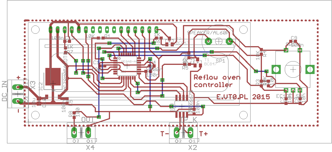
The pcb design is not ideal, but is good enough to work in finished oven.
Disadvantages:
-no ISP programming connector, or even test points :(. I workaroud this by bodge Kanda header with kynar.
-Also small imperfections like no mounting holes, T- from the thermocouple should be connected to gnd - this is simple to repair by a drop of solder or a wire.
-CS pin from MAX6675 should be connected to vcc via 100K resistor to allow programing atmega - they are on the same pins.
Software will be published on Github - link on the left <---
I will also upload to another github repository files from Eagle.
 J.R. Stoner
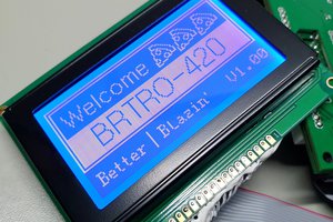
 Blecky
 Nick Sayer
 Miroslav Zuzelka