 DrYerzinia
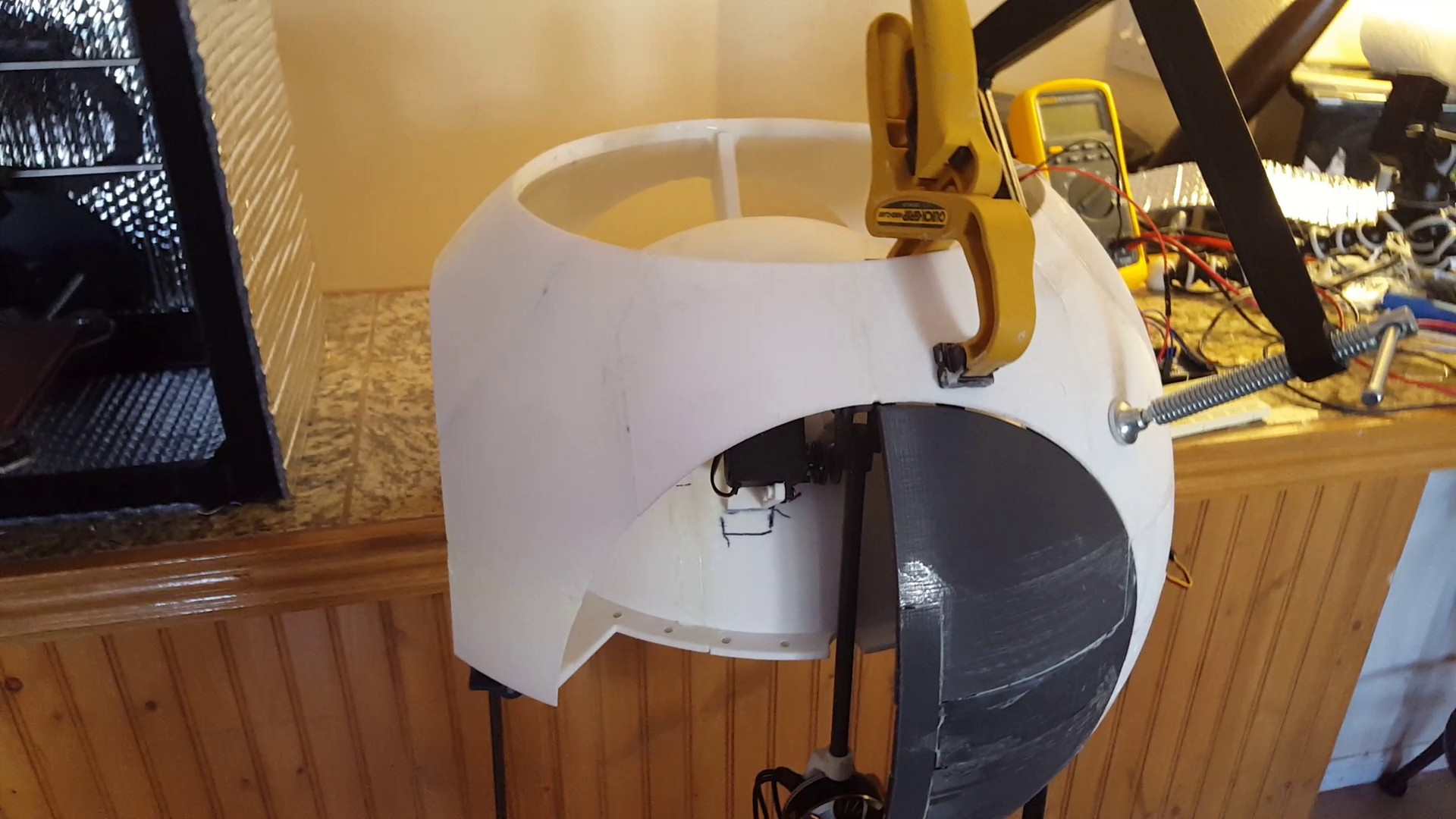
BB8's head will stay ontop of his ball body by driving around on it with 4 wheels.
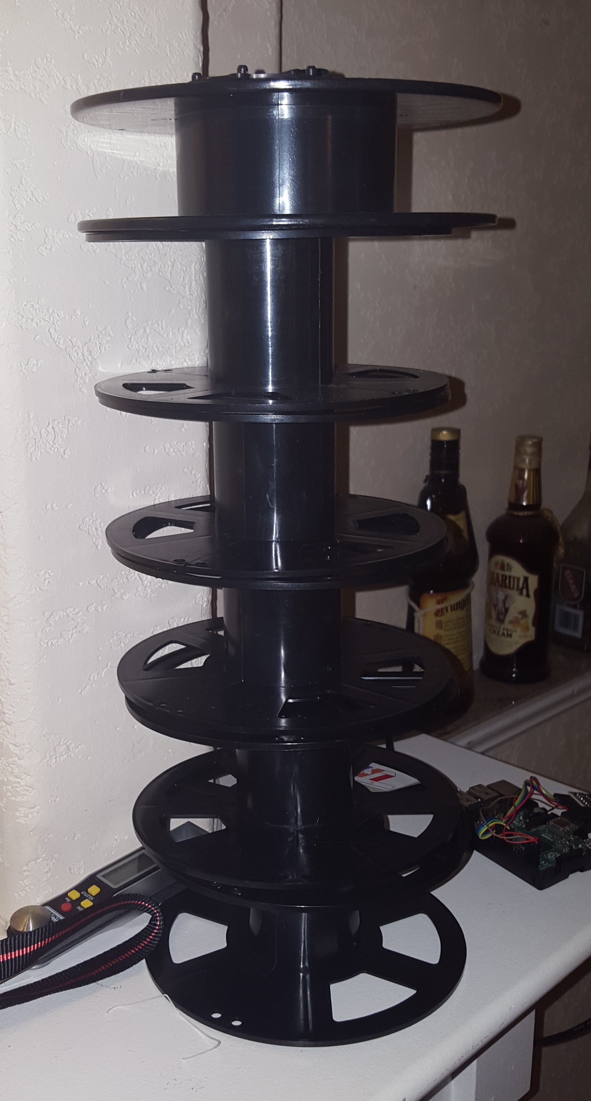
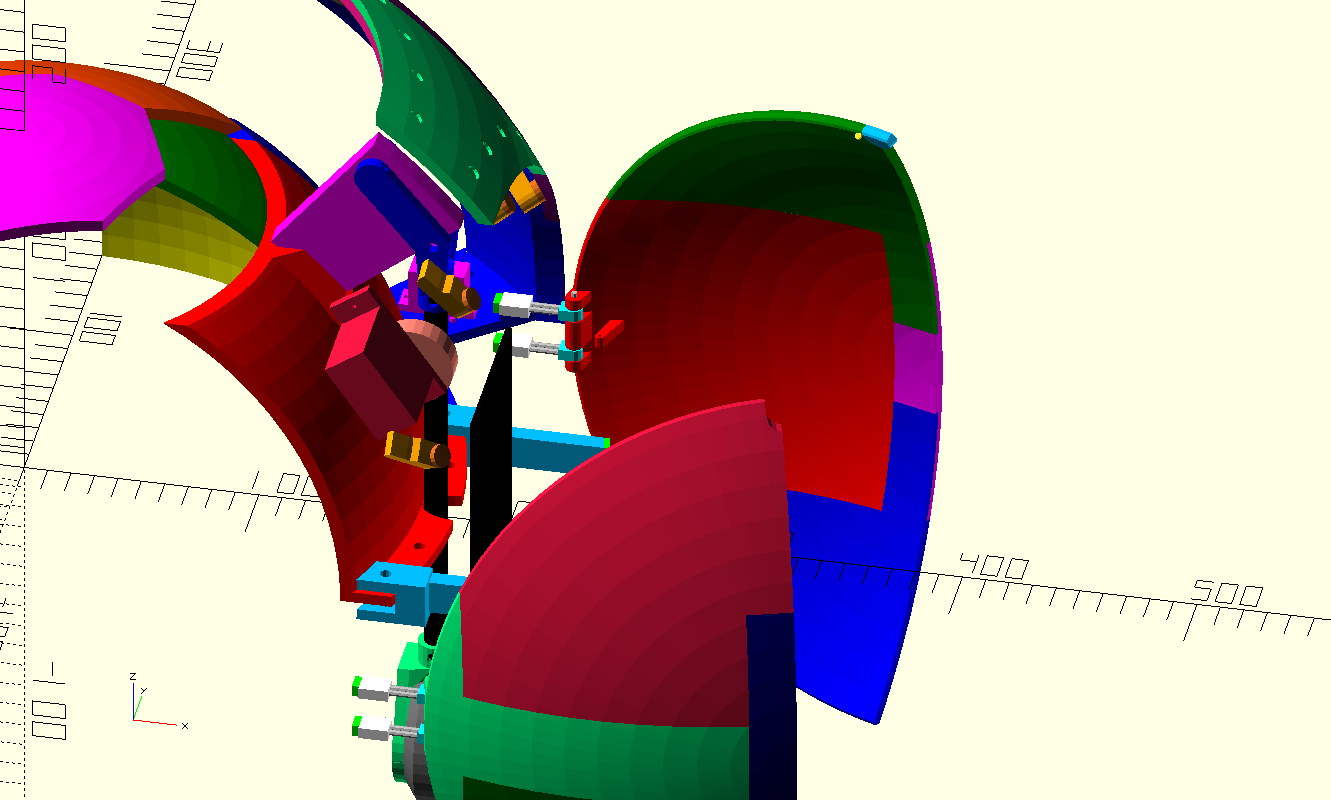
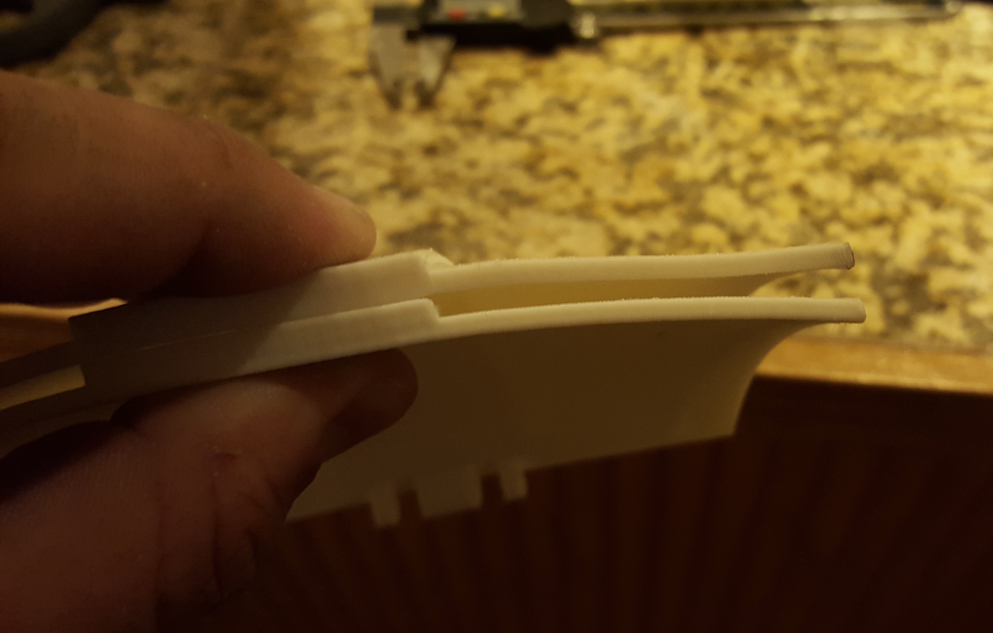
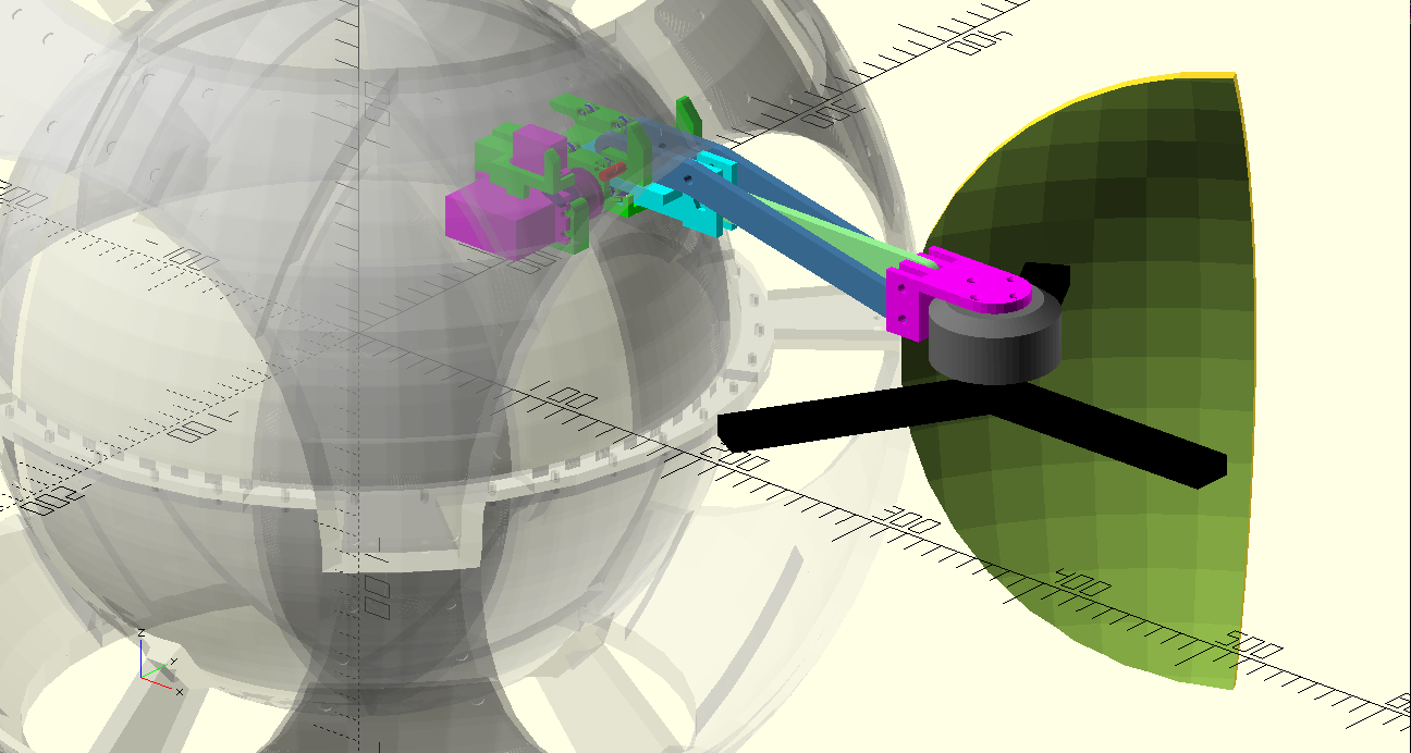
The frame is composed of 2 spheres one inside the other. This leaves a cavity in the shell 7.5 cm wide for gadgets and leaves the inner shell for the rolling drive system. For flight mode the droid will have to roll into the correct orientation where there will be magnets for the head to lock onto the droid body, as well as high current contact on the inner sphere to carry power to the flight motors from the battery which is used as ballast in the drive system. The orange circle will slide or hinge out of the way enough to allow the motors to swing out of the body and then close with a second tinier hinged section left open for the motor arm.


 ken.do
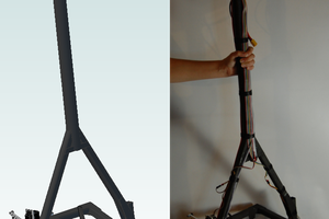
 zakqwy
 jellmeister
 Tobias
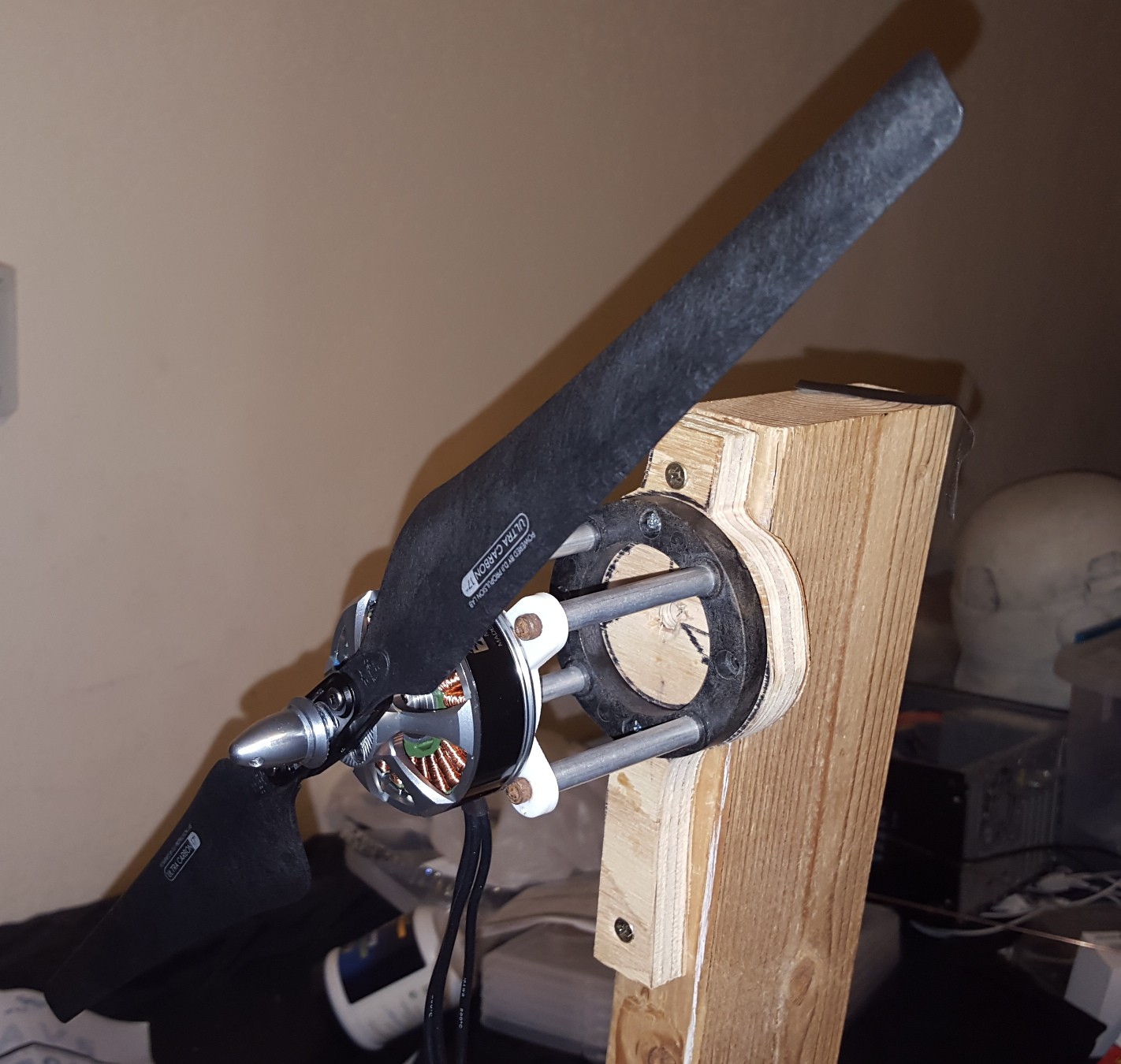
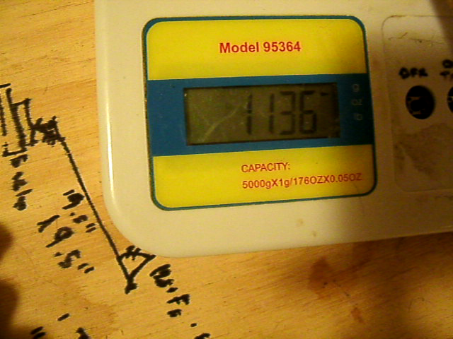
As a note, if the motors have a lifting capacity of 8lbs @ 100% throttle, you'll want your all-up weight to be around 50% of max-thrust (16lbs). You don't want to run the motors/electronics at 100%. You could probably get away with a 1.5:1 thrust:weight ratio if you had to, but 2:1 is usually the sweet spot.