 Nicholas Amrich
There are some improvements to make over this design:
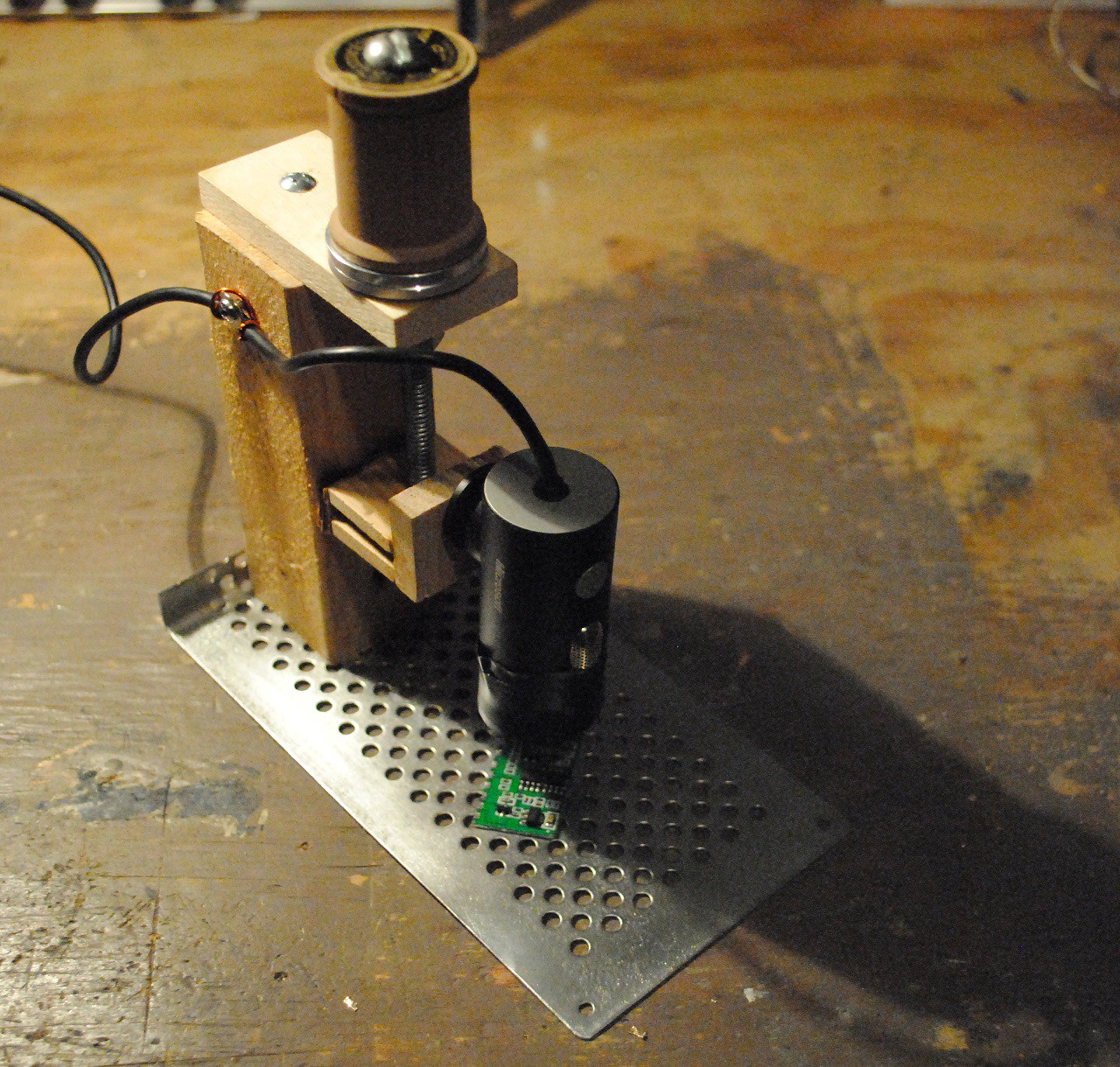
-Take apart the webcam and replace the existing lens with one of the magnifying ones. This should fix some of the image distortion.
-Build in some LED lighting to illuminate the board, removing the need for an external lamp.
-Find a combination of lenses that act like a telephoto (zoom) lens rather than a macro lens. This will allow you to have the camera higher up and reduce the chance of bumping it with the soldering iron.
 WJCarpenter
 Ted Yapo
 Wing Tang Wong
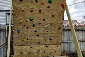
 Pete Hoffswell