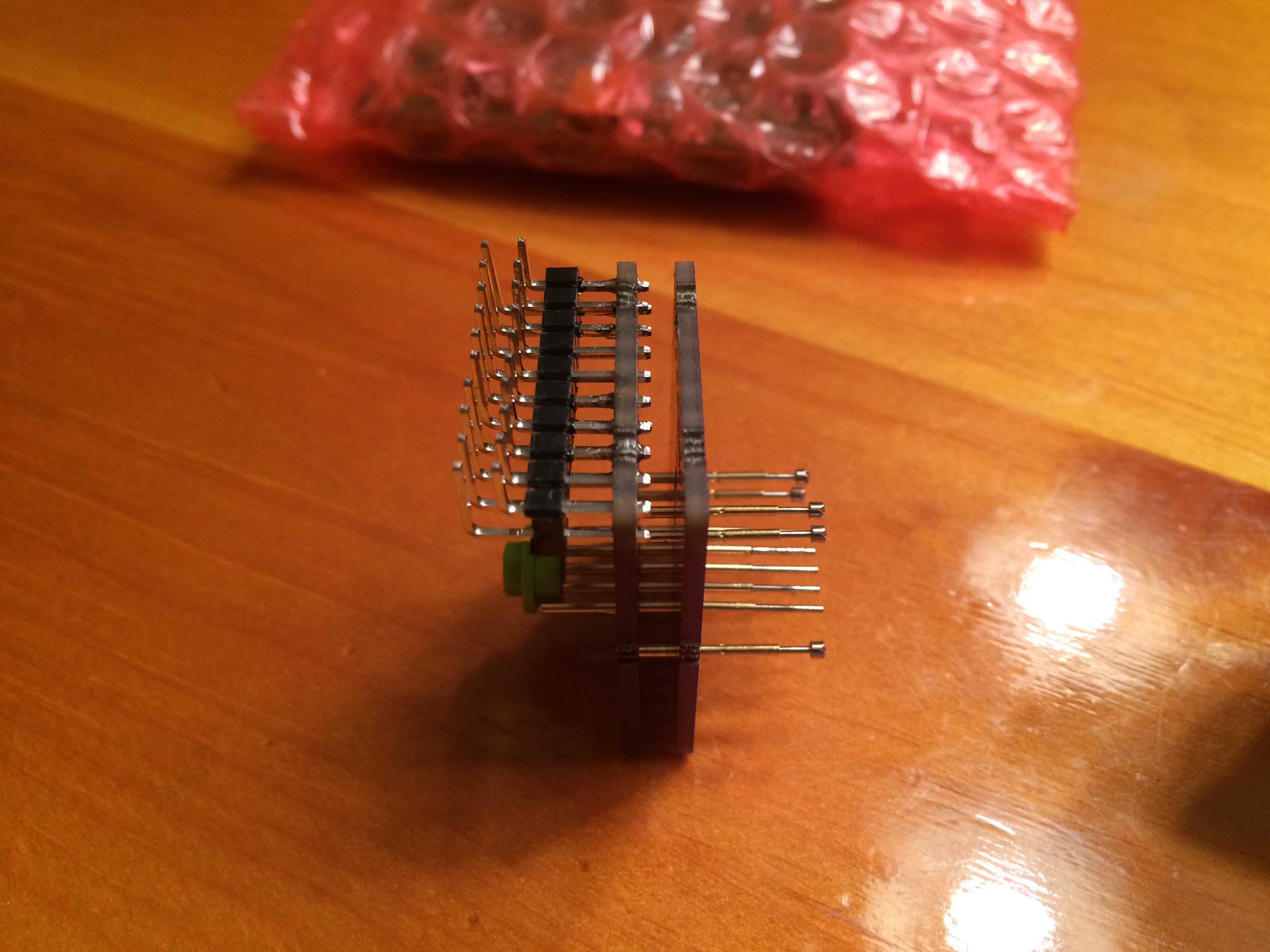
I finally got some time to work on this again. I put together the jig, soldered a blank CMIC and cap onto one of the boards, and tried to get it working with the dev kit; no dice. That's ok, I can still use the dev kit to program a chip then assemble it. First lesson learned: while the 3-pin headers look nice, there's not enough pad extending from the drill hole for the iron tip to reach. I had to use more flux than usual and just run the solder down the pogo pins until the heat spread to the pads as well. Ugly...
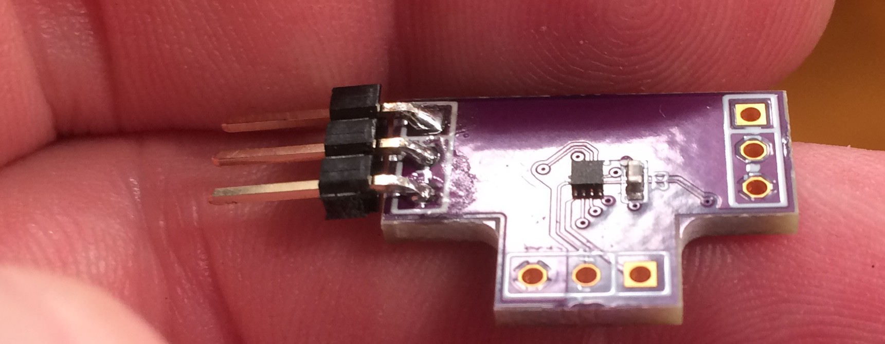
So, that was my next task. I'm glad I got the stencil, as it worked great. Since both components are on one side, it's easy enough to fry them. Second lesson learned: the capacitors are taller, and the small amount of solder paste left by using the stencil did not reliably adhere them. Other than that, the frypan worked great.
Next task: time to try it out. The DOut leg worked great. The DDelay leg flashed weirdly; With no delay, it appeared to be out of sync. Progressing lights were three-LEDs wide instead of two, illumination was too high, and coller was off. On the plus side, the overall pattern was recognizable. I suspect it's not enabling output on a 24-bit boundary, but on some other point in the data stream. Third lesson learned: don't program and populate all your prototype boards until you know if it works or not.
Time to break out my new logic analyzer.
Discussions
Become a Hackaday.io Member
Create an account to leave a comment. Already have an account? Log In.