This project is built using the following parts -
- Arduino Uno (or Sparkfun Redboard)
- HC-SR04 echo ping sensor
- 5 mW laser module from Sparkfun (COM-09906)
- PN2907A PNP transistor
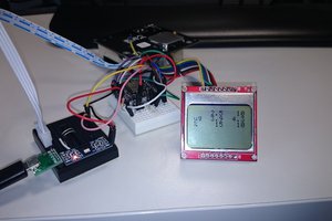
- Graphic LCD (84x48, Nokia 5110 from Sparkfun, LCD-10168)
- The button is connected to pins 2 and GND, no power
- The echo and trigger pins from the HC-SR04 are connected to pins 7 and 8, powered by 5V
- The LCD is connected to pins 4, 5, 6, 11, and 13, powered by 3.3V
- The transistor is connected to pins 9, and 5V, and the laser
The Arduino code initially turns on the laser for aiming, and waits for the button signal.
When signaled, the laser will blink, and the screen will display Measuring, followed by the distance measured in cm. The loop then repeats and waits for another button push, while displaying Idle on the screen.
Some of the issues I had with this project were -
- HC-SR04 ping sensor very sensitive, most of the time, I couldn't get a reading, but after switching the the NewPing library, I've had better results, still fails about 20% of the time
- Laser was too powerful for the first transistor I tried (4401), but after switching to the 2907A, I was able to power the laser
- Adding the LCD required me to use and enable the SPI bus. Initially I had the HC-SR04 using pings 11 and 12, but after adding the LCD, the HC-SR04 stopped working. I narrowed the line down to "spi.begin" which stumped me. I was convinced enabling SPI and the LCD somehow was interfering with the interrupts for the HC-SR04 and NewPing library. I read some of the details of spi.begin for the Arduino and realized when you enable SPI on the Arduino, it uses pins 10, 11, 12, and 13 for SPI - which I was trying to use for the HC-SR04 sensor. I reconfigured the pins, and moved the HC-SR04 down to pins 7 and 8, and the HC-SR04 started working again. Lesson learned.
- Laser is still WAY too bright - I might try to use a voltage down-stepper to lower the voltage as much as possible
- LCD is still tricky to write to - I was having trouble displaying the last 5 measurements on the screen and ended up giving up for now.
 k
k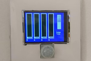
 Jaques Lopes Schroeder
 Tom Meehan
 Hulk
Hulk