0%
0%
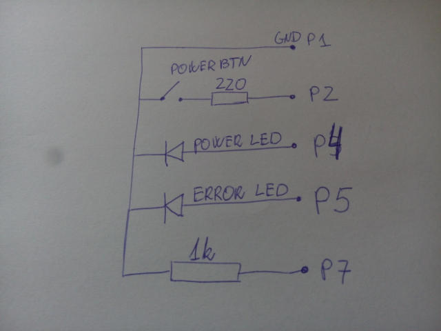
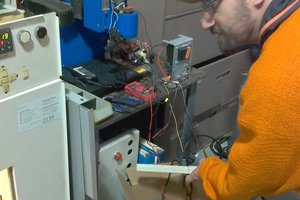
Canon all-in-one inkjet emulator
Arduino based all-in-one inkjet emulator for those that want just to use the scanner when the printer part failed
Become a Hackaday.io member
Already have an account? Log in.
Just one more thing
To make the experience fit your profile, pick a username and tell us what interests you.
Pick an awesome username
hackaday.io/
Your profile's URL: hackaday.io/username. Max 25 alphanumeric characters.
Pick a few interests
Projects that share your interests
People that share your interests

 Ross Bochnek
 CLo
CLo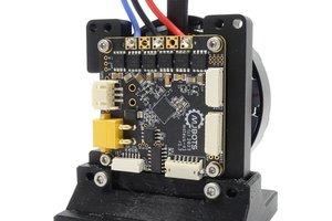
 Josh Pieper
Hi there! I am also interested to work with you all. Can you please have some time to share to work toward the project.