The first goal was to emulate the paper feed system.
The principle of it is fairly simple. It uses closed loop control. Main controller controls the motor driver and reads the data from quadrature encoder. This way the speed, direction and duration is controlled.
Apart from this, there are a few sensors for paper position, but all of those does not affect the startup of the device in any way and can be disconnected. In MP210 case what is needed is just to cut the ribbon cable that goes to those paper position sensors. Location of all the connection on the main control board is marked in the photo (in the main gallery of the project).
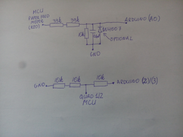
To emulate the quadrature encoder signal, Arduino UNO was used (mostly for availability). Since the printer uses DC motors, for speed control PWM signals are used. Measuring DC equivalent voltage going to the motor one can see that it has 3 levels: Fast Forward, Slow Backward, Fast Backward. To measure this with Arduino a voltage divider with a RC filter was used, since the drive voltage of the motor is ~30V.
Based on the direction and speed of the motor quadrature signal is generated and fed into the main printer controller. For this another voltage divider was used, since the quadrature encoder had ~3V voltage levels. The frequencies of the quadrature signals are as follows:
Fast Forward or Backwards ~3 kHz
Slow Backwards ~250 Hz
By the use of some really crude code the printer now starts up without the paper feed motor and related hardware.
Schematics for the circuit is very basic and shown in the picture. Paper feed quadrature encoder has a 4 wire ribon cable going to it. Two middle ones are signal wires, while the outside ones are 3V and ground. 3V wire is marked with a red stripe. In the uploaded code, pin 3 connects to the wire closer to the 3V wire. While pin 2 of the Arduino the other middle wire.
Discussions
Become a Hackaday.io Member
Create an account to leave a comment. Already have an account? Log In.
Great project. I wonder what you made out of a strange chip on the printer control panel, namely k12395 from NEC. I scoured the net for its datasheet in no avail.
Do you have any idea about it? Thanks
Are you sure? yes | no