 Daniel Grießhaber
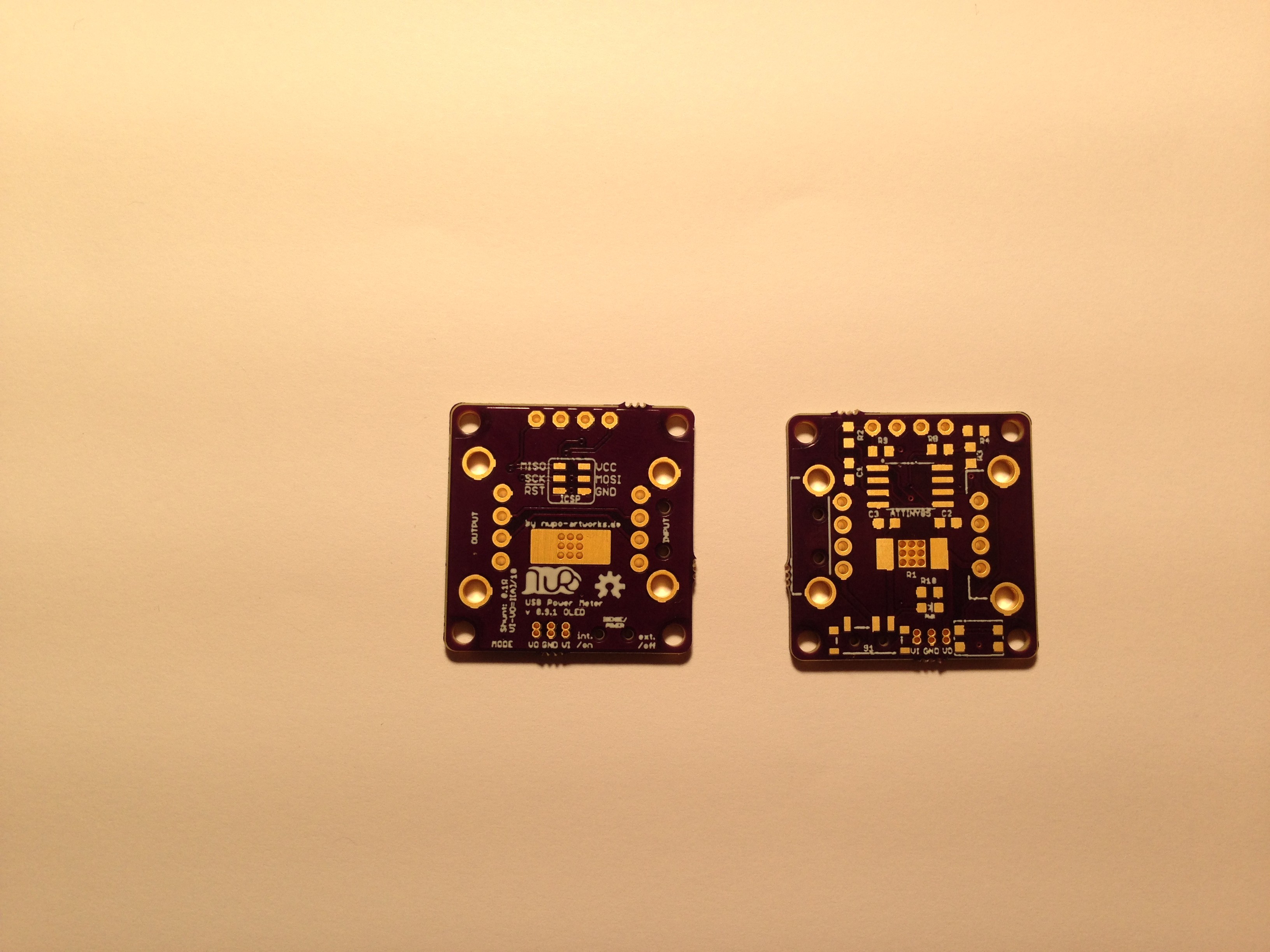
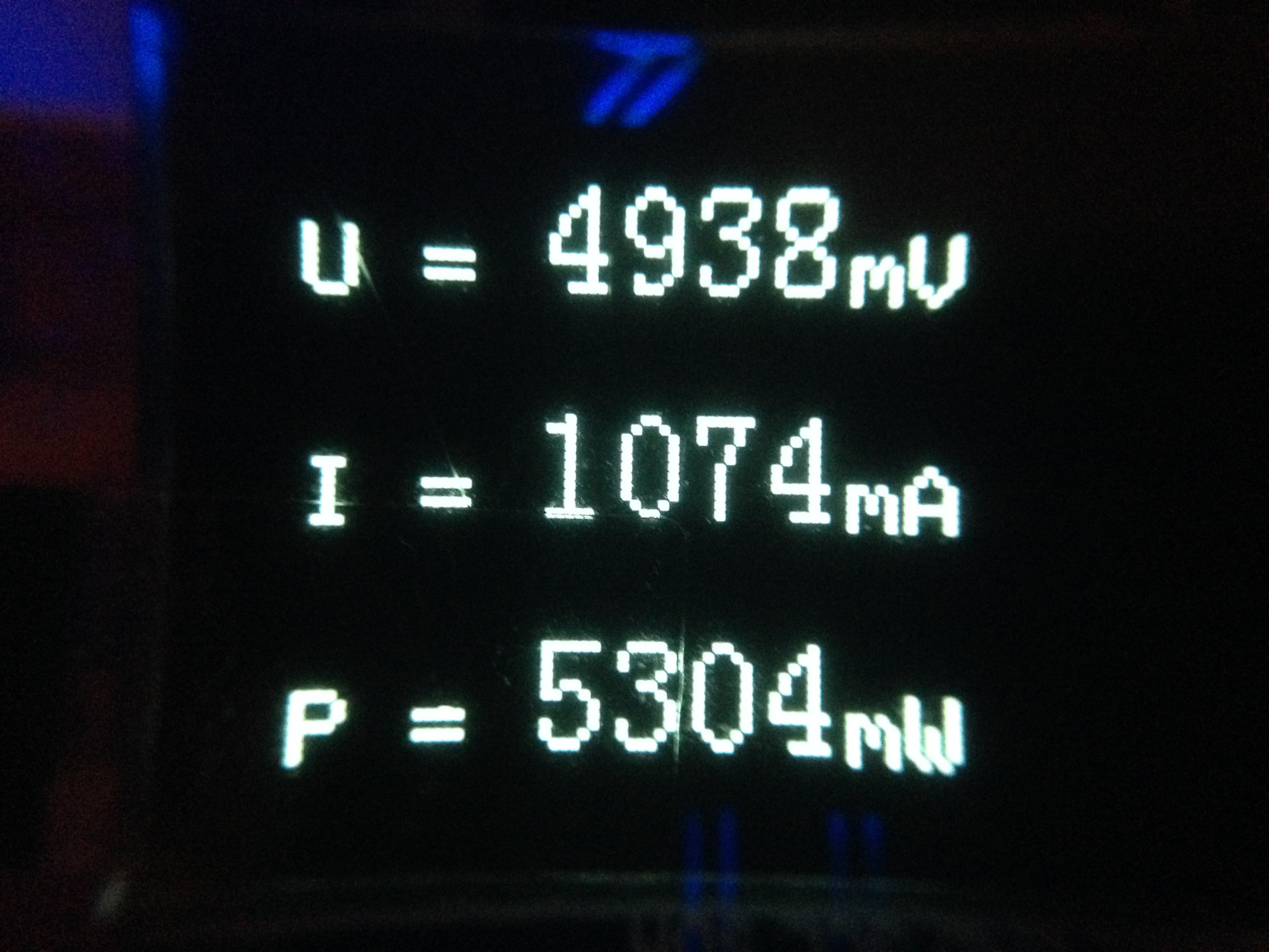
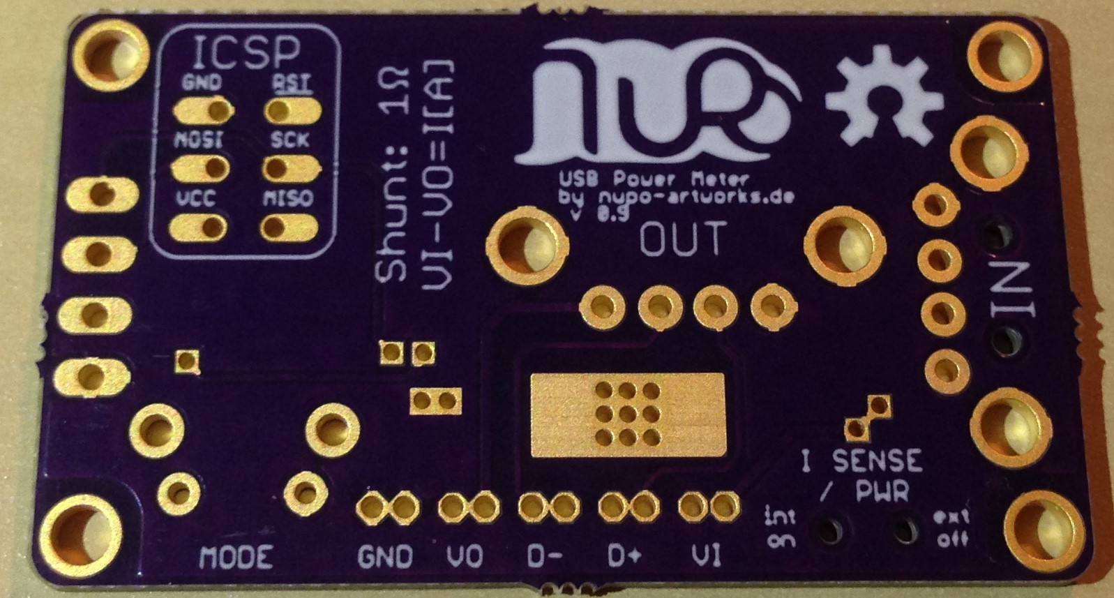
To measure the Voltage and the voltage drop I needed a stable reference voltage. This means I can not power the ATtiny without regulation and use this voltage as a reference. Instead I've chosen to use the internal 1.1 volt reference the ATtiny offers. This way I need to split the voltages down so the are around that 1.1 volt area instead of the +5 volts of USB.
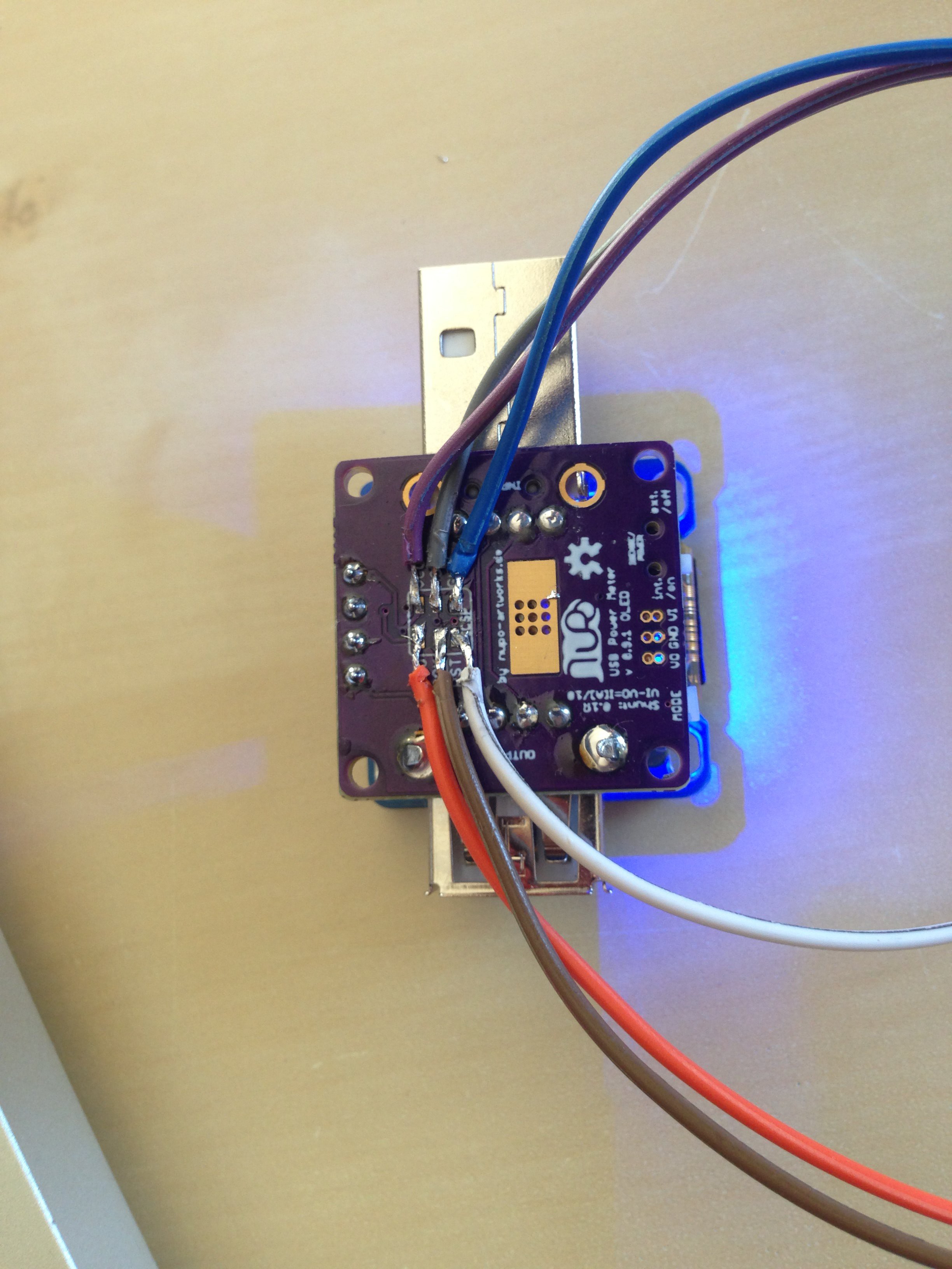
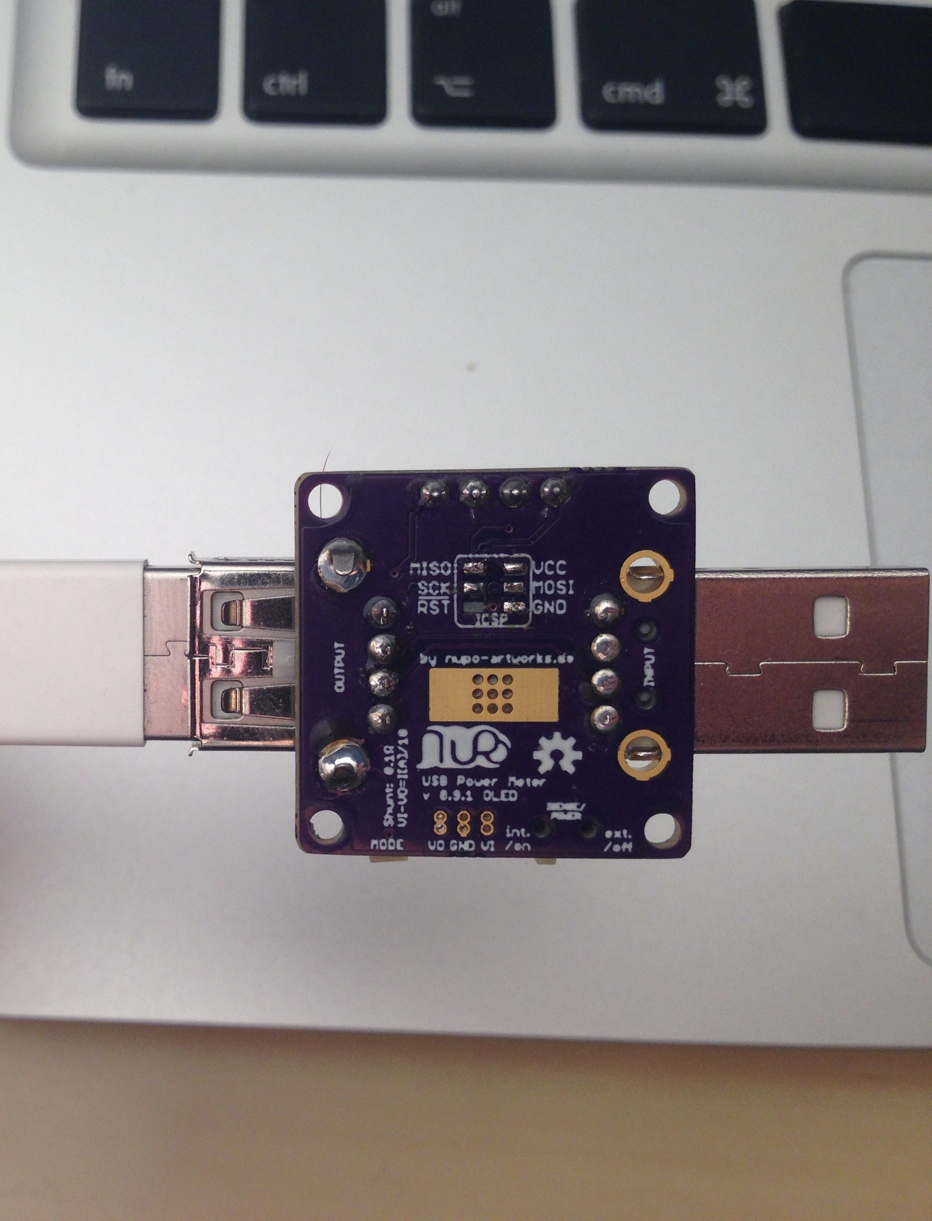
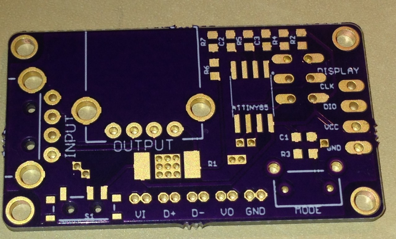
This Powermeter has a section of Testpoints where you can easily attach probes to different pars of the system, so it can be used to tap off any of the USB lines.
Also there is a switch that acts as a power switch for the meter and disconnects the shunt resistor so you can use your own multimeter to measure everything


 Jeff Cooper
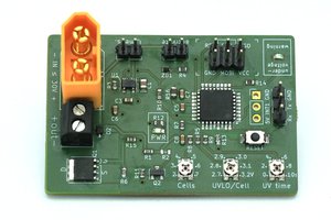
 Jan
Jan
 Edward Li
 Torbjörn Lindholm
Nice to see someone trying to make a useful meter. The ones on the market are no good for measuring small currents and are not at all hackable.