 Daniel Grießhaber
While writing the firmware for the 7 segment version I noticed a design flaw in my layout. I was using a resistor network to attenuate the voltages measured at the shunt by a factor of 5. I thought this might be necessary because I was using the 1.1V reference of the ATTiny85. This would get me a dynamic range at the ADC in single ended mode of which would be enough to measure the ~5V that USB should give us. However, for the current measurement I use the differential mode of the ADC which has a switchable gain of 20. The formula to calculate the current given a measured digit count is therefore
with
and
Even with the gain switched on, I would get a dynamic range in the current domain of
which would result in a resolution of
which is OK but far from being good in the <100mA range. This also would enable me to measure up to
when the gain is switched off. Since the meter does not support USB-C I do not expect such high currents (Even USB-C cant handle 275W@5V).
So what I did was to remove the attenuation network. However, this means I can not measure the supply voltage with the 1.1V reference, and would result in always reading 1024 when applying the expected 5V to the input. Not be able to measure the input voltage however would mean I would not be able to measure the power consumption either which would make the device a current meter only. Thats kind of useless, however I did not have any more free pins on the ATTiny so what should I do?
After a bit of thinking I finally came to a solution and I want to say it is quite clever because I only have to attach one component. The only pin that was not doing anything important was the input pin for the mode selection switch. However I did want to have a switch to select the current mode rather than cycling through the modes on a fixed interval.
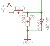
So what I came up with is using the 10k pull-up resistor that was already there as one part of the attenuation divider. All I had to add was another 2k resistor to ground. This gives me a high impedance, x5 attenuator. The function of the switch is not influenced either. If the button is pressed, the 2k resistor is bridged, shorting the input to ground, meaning I should get a really low value while reading the pin with the ADC. If the button is not pressed, I should always read a value greater than, lets say 256 which would mean that I only get 1.5V from the USB port. At this supply voltage I can expect that the meter and the device do not work properly anyway so nothing to worry about false-positive button switches.
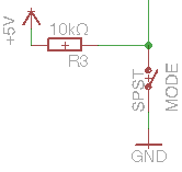
Here is the circuit before the mod:
and here with the added resistor:
Discussions
Become a Hackaday.io Member
Create an account to leave a comment. Already have an account? Log In.