Alex
Alex-
Some further ideas - by al1
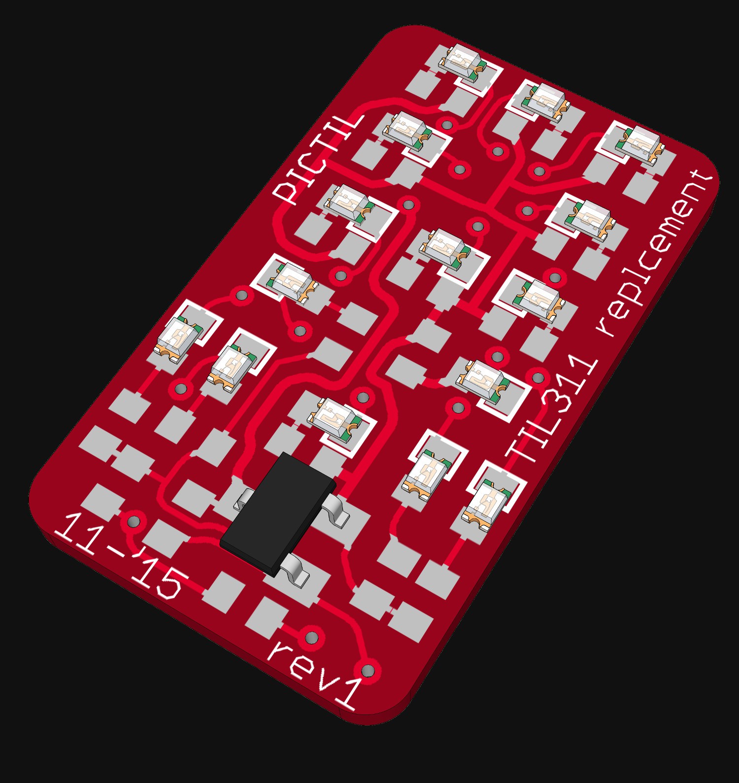
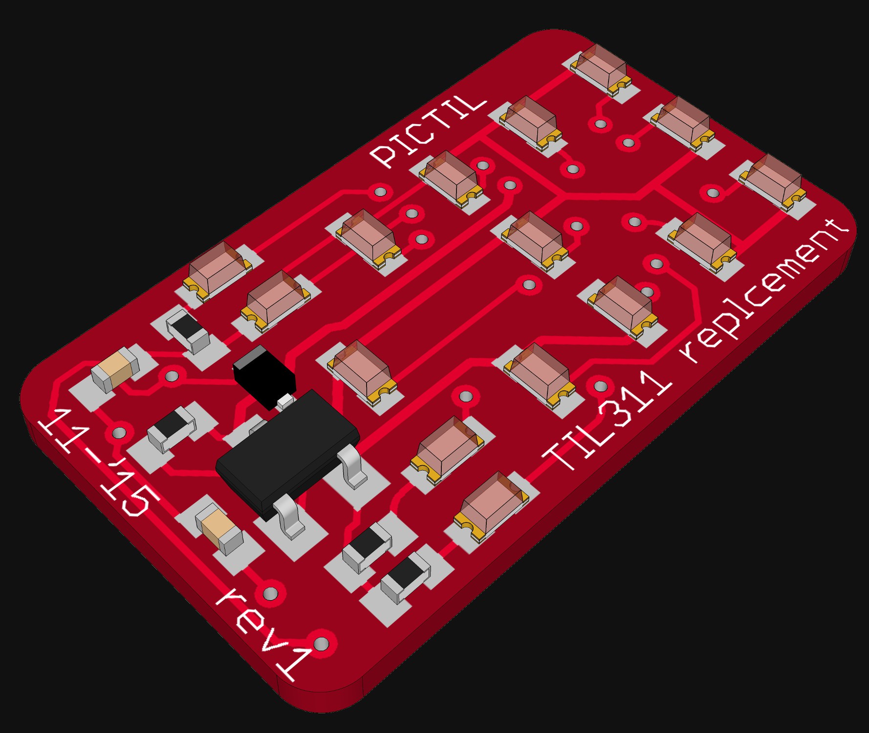
11/03/2015 at 21:04 • 12 commentsAs written previously on this page. I did some PCB layouting on this project. First more to test whether it is possible to make an drop in replacement out of a tiny PCB with the same size as the original TIL311. But think I did now have a first version ready. I did first started with tiny 0201 LEDs but I think they are very difficult to solder. So I moved over to 0402 LEDs. This also brings you bigger numbers with less LEDs. Here some renderings (created with eagleUP and sketchup) of the PCB:
![]()
![]()
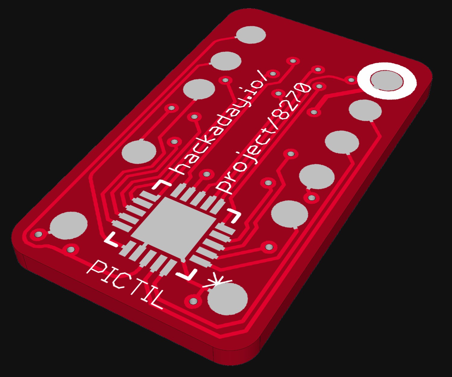
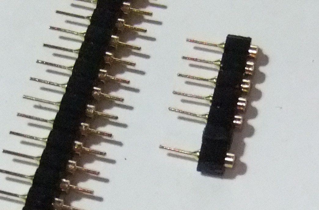
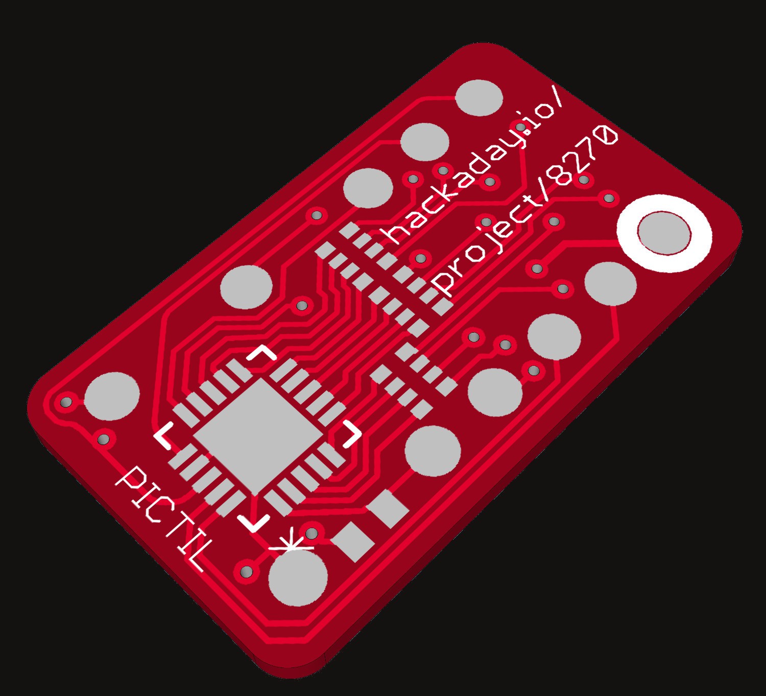
In my design I used the PIC suggested by @Yann Guidon / YGDES. And a p-channel mosfet to get the blanking function. The mosfets and the LEDs are on the top side and the microcontroller on the bottom side. As you can see on the picture pin headers must be SMD. There was no place left over for THT pin headers. Sadly pin headers like these does not exists (correct me please if I am wrong). But you can make them yourself out of more normal THT ones. Here a picture of a test (on the left the original and right the modified for SMD mounting):
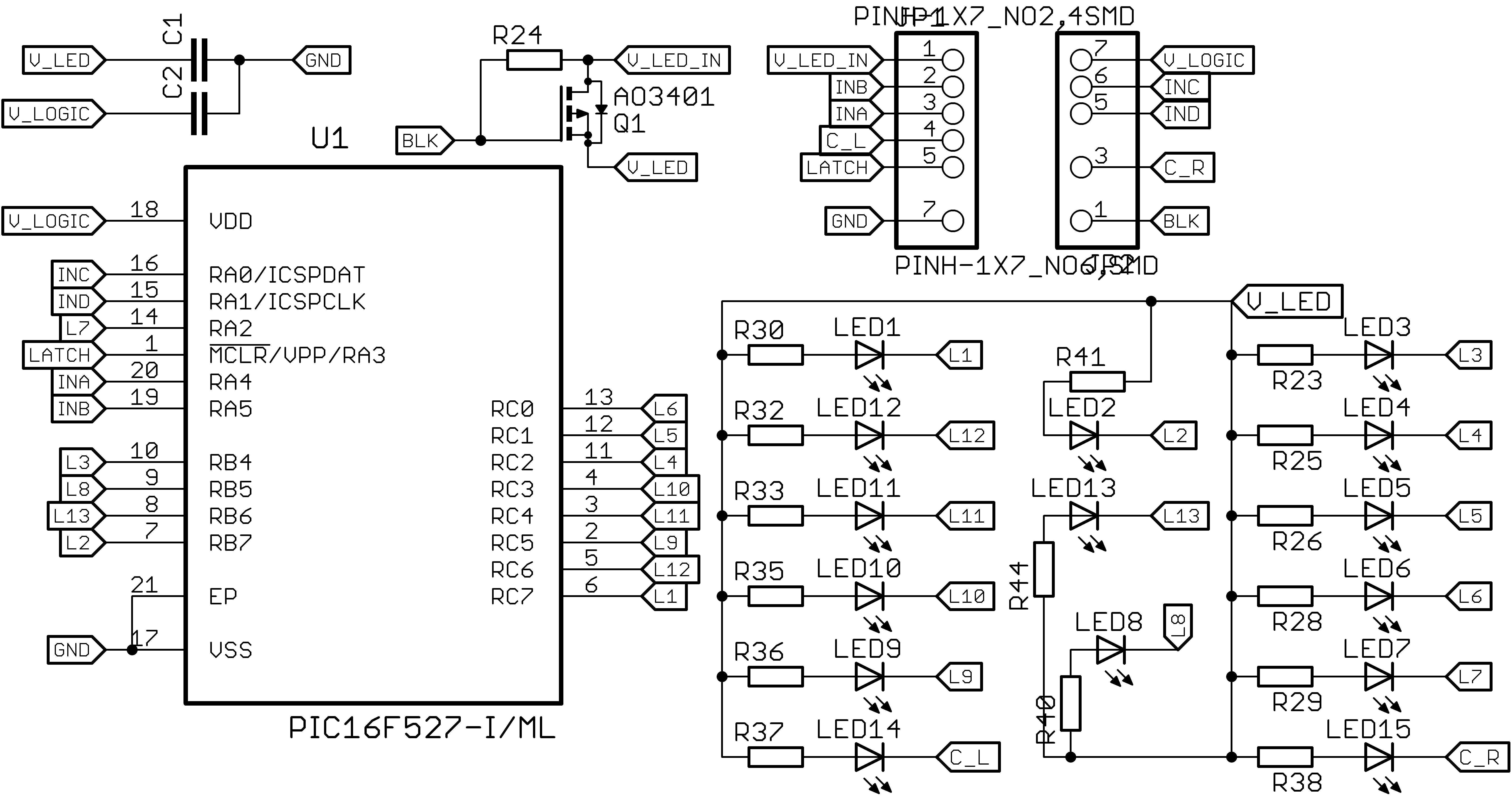
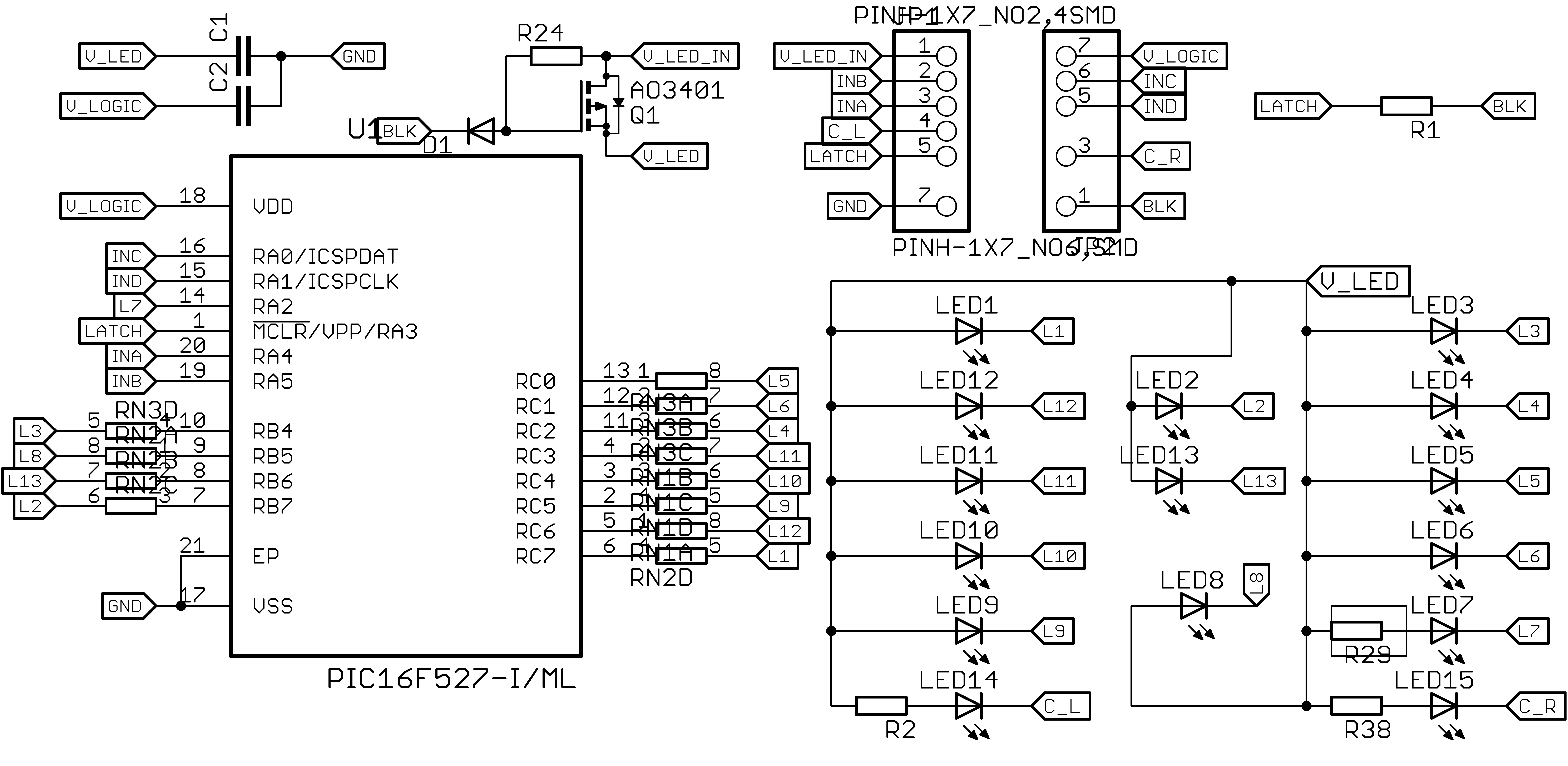
And here is the schematic of the PCB. All pin used for programming the PIC are used as inputs, so the can be accessed.![]()
![]()
So that was all for today. If you have any suggestions, ideas or found mistakes please let me know.
-
Update - by al1
11/07/2015 at 15:03 • 13 commentsThe comments on the last log were good. Thinks I changed:
- resistor Arrays
- resistors on the back
- diode at the gate ( I hope right)
- switched to 0603 LEDs (resistors and capacitors are still 0402)
So here are some pictures as an update:
![]()
![]()
![]()
-
Quick update - by al1
11/08/2015 at 22:48 • 10 commentsJust quick update, because I will order first prototype boards now, because the square inch prize requires assembled projects.
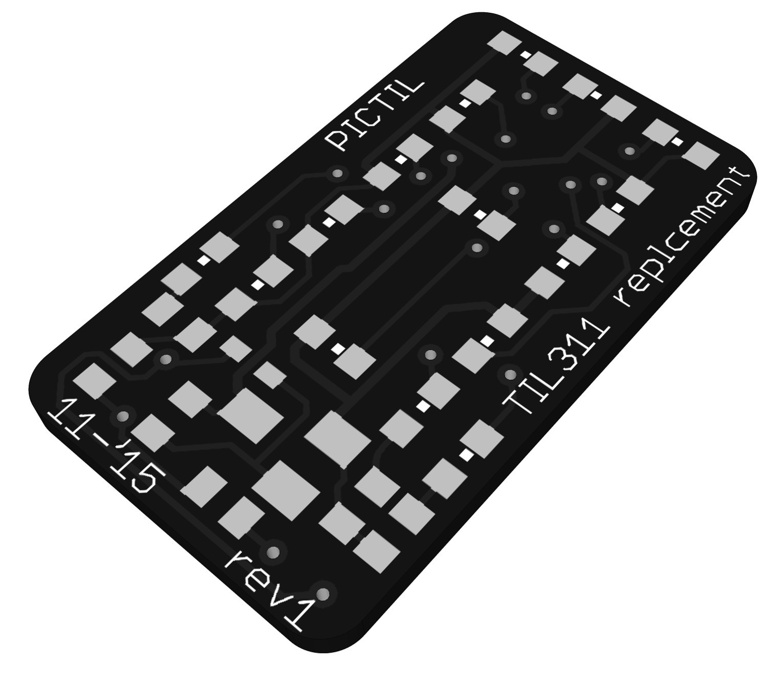
The only thing I changed to last time is the orientation of some LEDs. In this first prototype I will not try charliepixeling or scanning, but maybe later (I will kept that in mind). Out of curiosity I tried black solder mask in the renadering and ( @Andrew Starr ) this looks quite good.
![]()
-
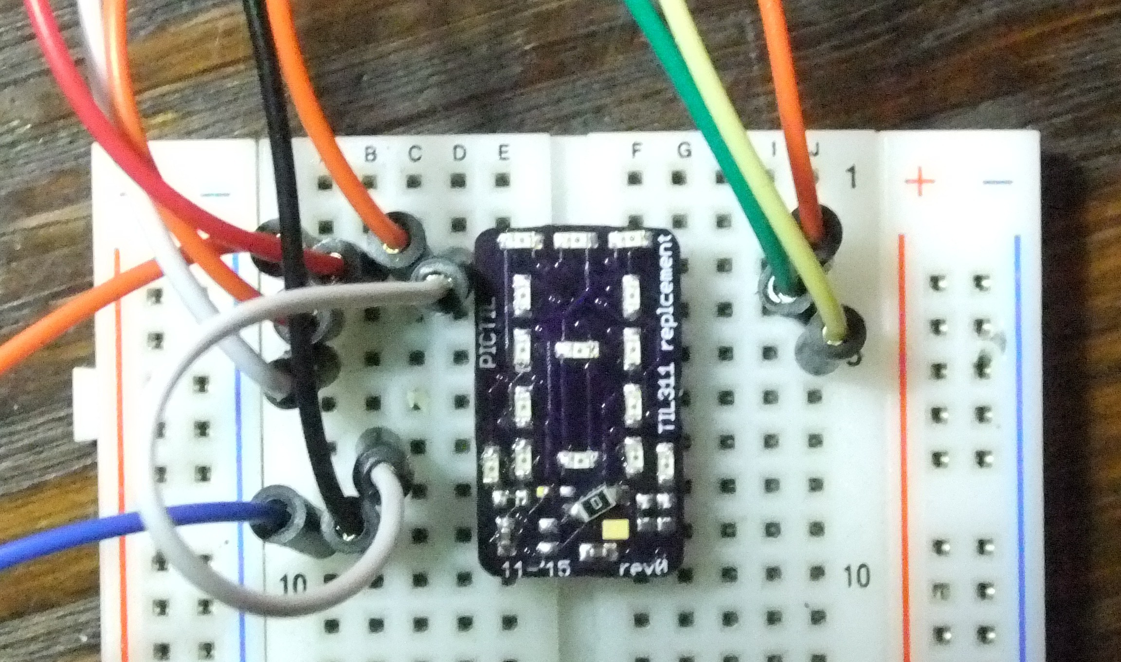
First software - by al1
11/28/2015 at 21:57 • 5 commentsWhile waiting on the PCBs I started to program the software. This was also the first time I did use PIC controllers so I was a little bit slowly. And at first PICs were a little bit confusing. Not all features do work yet but the basic functionality (decoding four inputs into led signals) is working. Here is some photo of my setup:
![]()
I will upload the software at bitbucket. So if anybody finds some mistakes or do have suggestions please write them! But note this software is not ready yet.
-
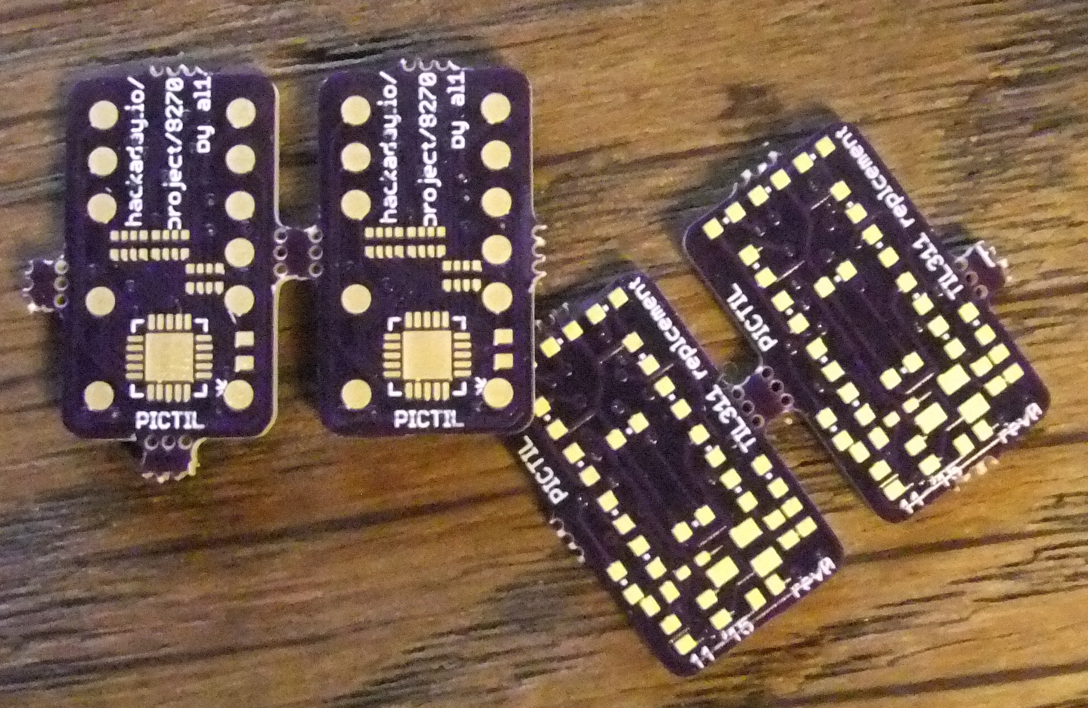
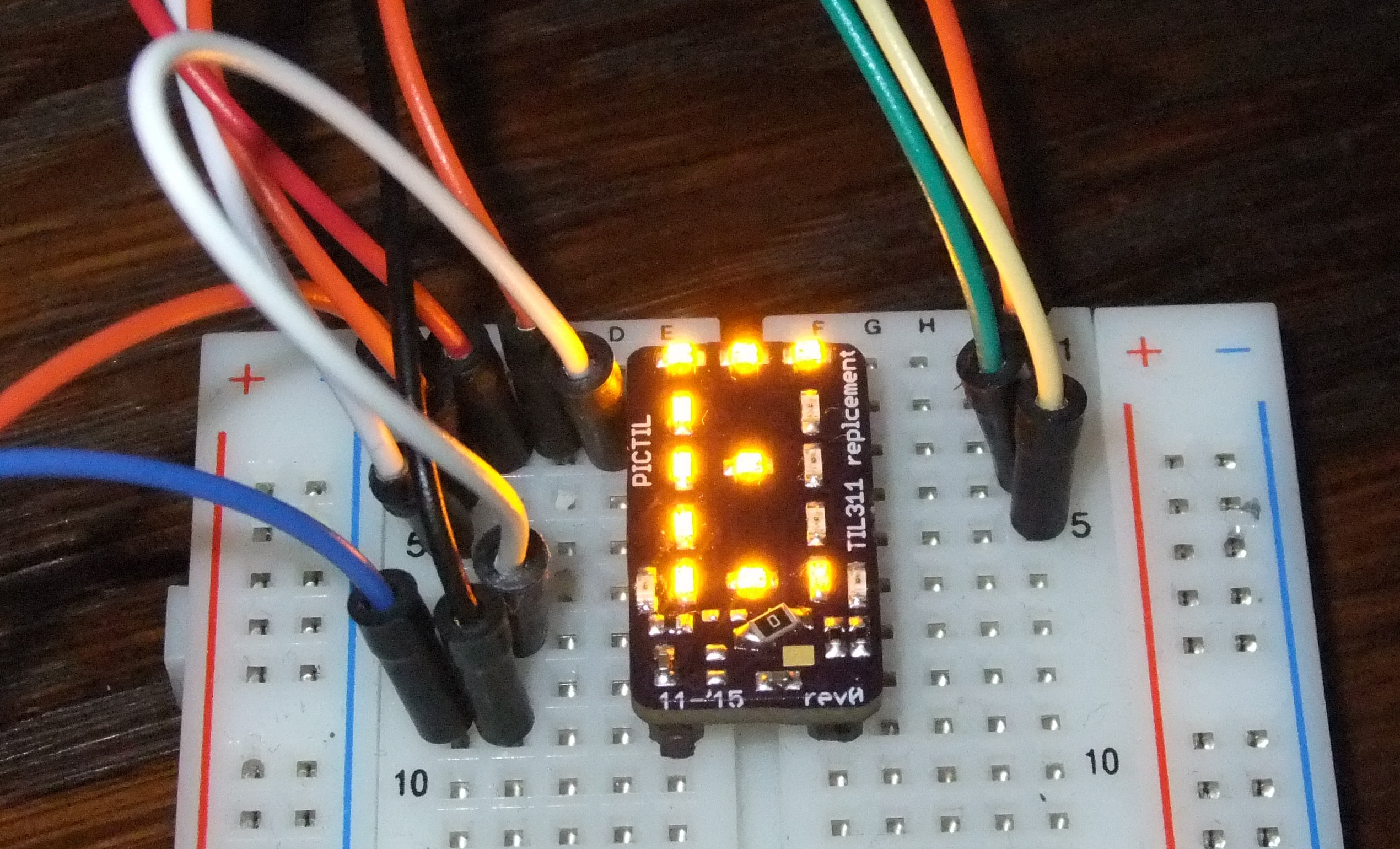
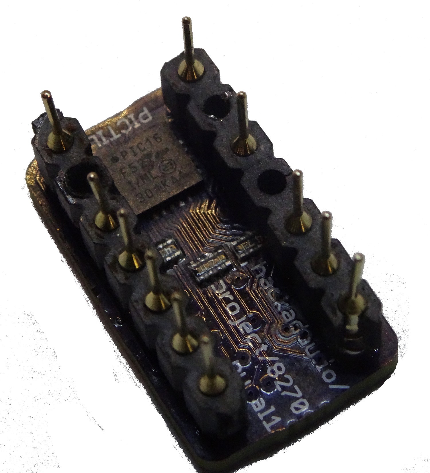
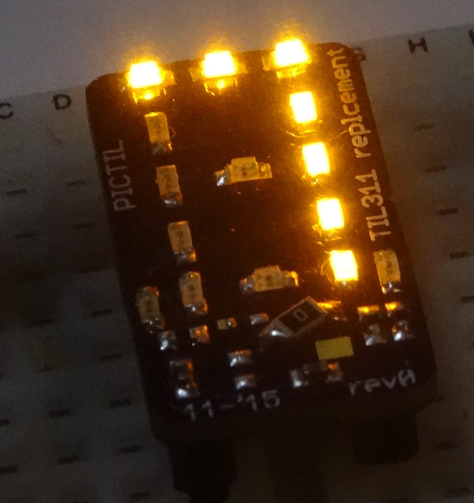
PCB arrived!!! - by al1
11/30/2015 at 18:25 • 11 commentsToday the PCBs did arrived. I did also soldered the first and it works. The software is still not ready (for example the latch input is still missing).
![]()
![]()
![]()
I will post some higher quality pictures and close-ups of the PCB later this week.
-
some video
12/07/2015 at 20:49 • 1 comment -
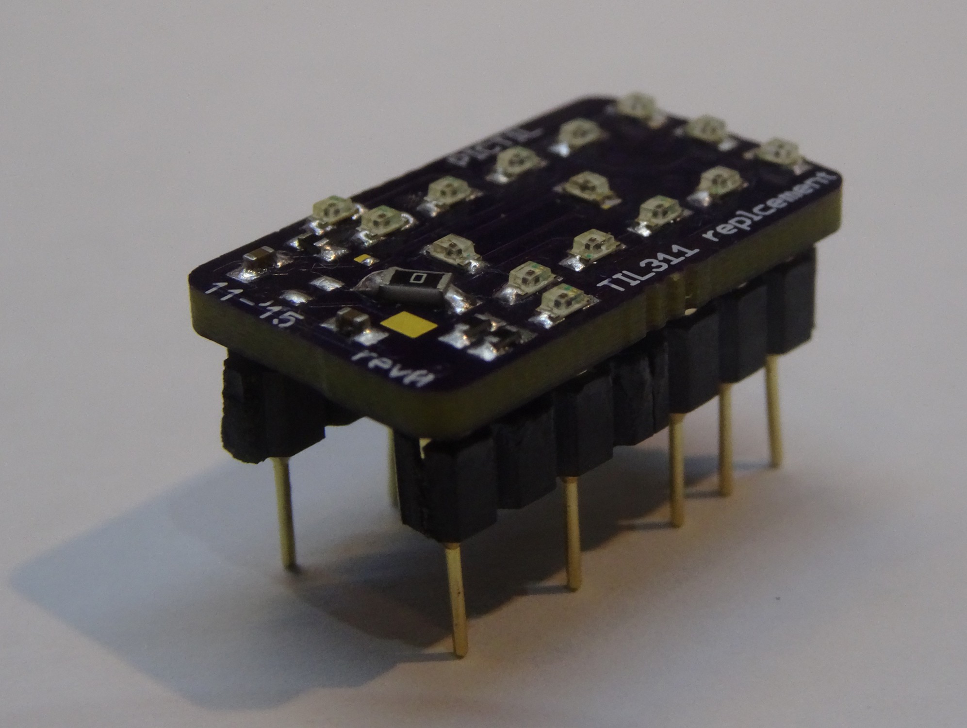
some additional pictures
12/07/2015 at 21:21 • 0 comments![]()
![]()
![]()
-
software update
12/22/2015 at 16:06 • 1 commentI did upload a new software version to the bitbucket repository. Now the input latch is supported. And I fixed also the wrong order of the input Pins, which I did noticed when comparing it directly to an original TIL311.
The latch pin is slower than at the original TIL311. This can be already noticed when controlling this pin manual by plug/unplug the wire on a breadboard. One thing I will try to fix that is a external interrupt triggered by a negative edge on the latch pin (RA3 on the PIC).
-
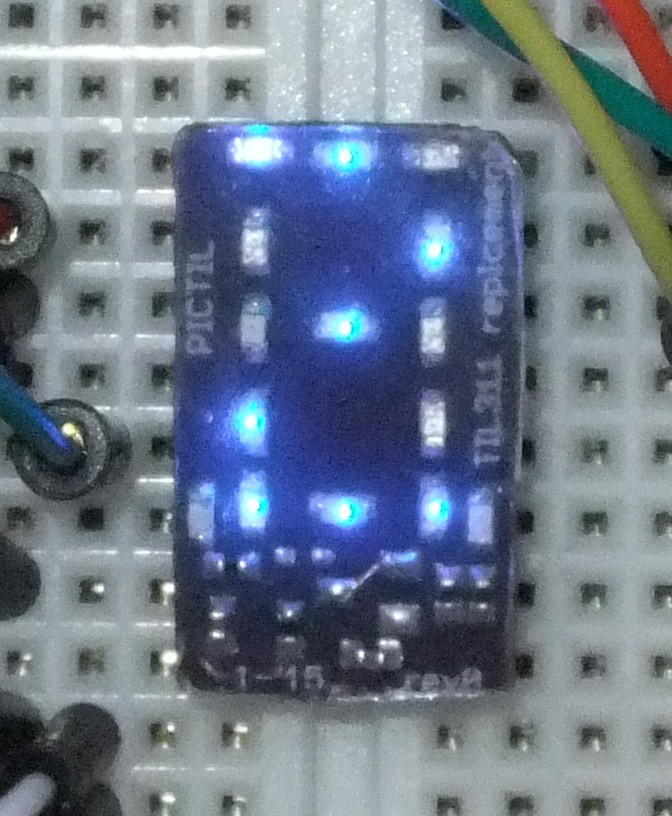
some errors - errata 1
01/08/2016 at 17:25 • 1 commentWhile building a second board I did noticed some issue.
- There is I mistake in the schematic and because of that also on the circuit board. I should had noticed that before but source and drain are interchanged.
This can be fixed by not using the blank-circuit and bridging the transistor by a 0 Ohm resistor (like in picture posted before). - The mounting of the pins is mechanical very weak. I did have a lot of trouble with with it.
There is no good workaround for this just be careful and/or use some hot glue.
The second board is with blue leds. And I did also experiment a little bit with molding the whole module with hot glue. I will take some pictures soon and write about this in a next log. Here is a "spoiler" picture:
![]()
- There is I mistake in the schematic and because of that also on the circuit board. I should had noticed that before but source and drain are interchanged.
-
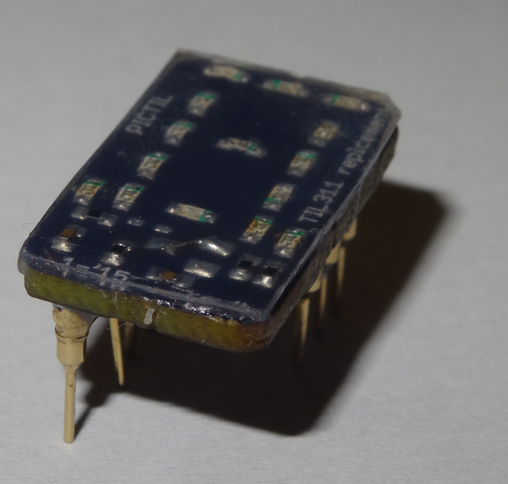
some pictures of the molding
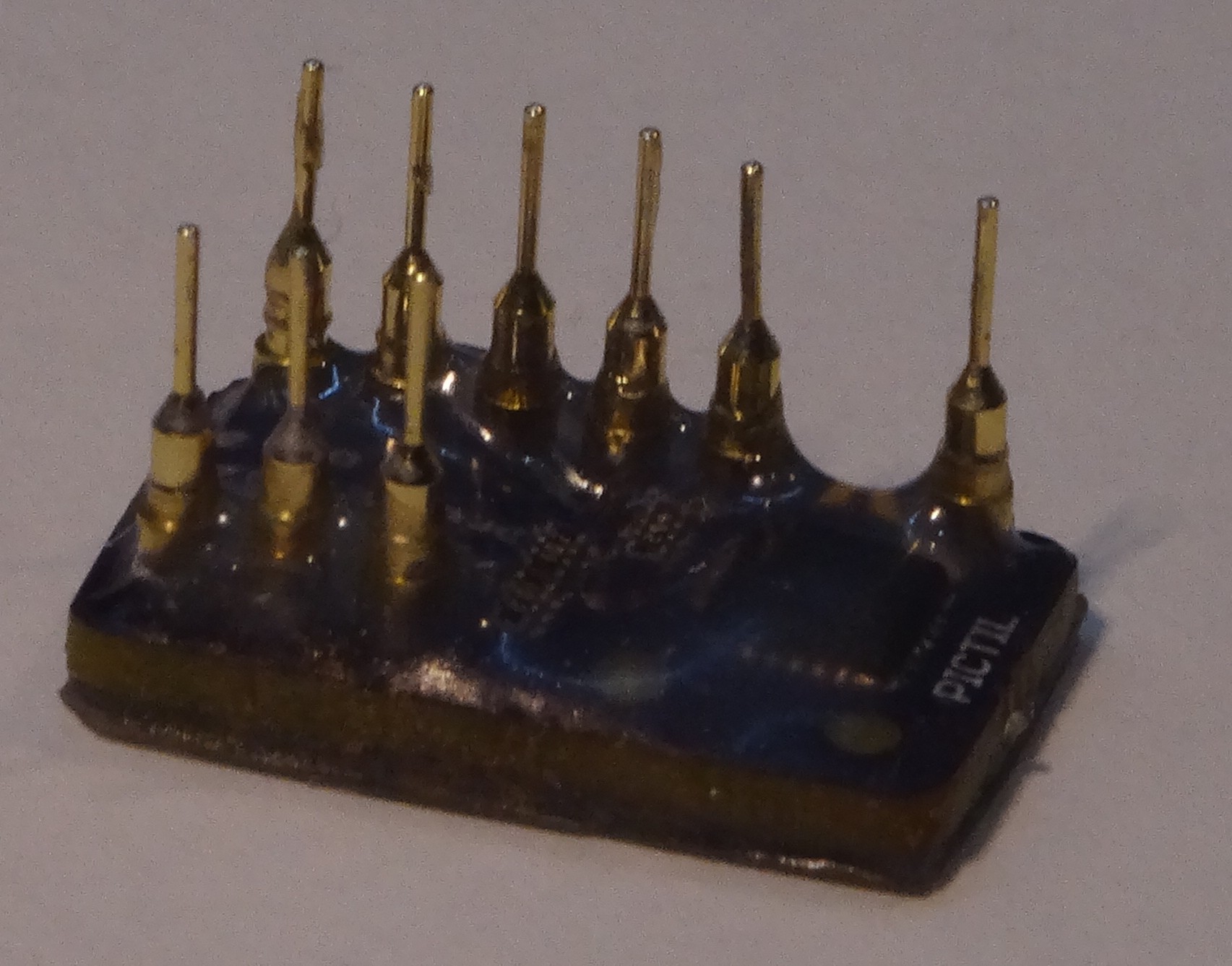
01/24/2016 at 16:10 • 0 commentsAs written in the last log I did experiment with molding the PICTIL. I used hot glue for that. I know this is not the best solution, but easy to handle and it was available. The top surface is a thin acrylic sheet glued on the PICTIL. The good thing about hot glue is it stays liquid when applying hot air. So you have some time to reduce air bubbles and do some rework.
![]()
![]()
I am not not happy with this SMD mounting of the pins as you can see in the last picture they do break off easily.
I did also some work on a new version with THT pins and the same number of LEDs as the original. More in a coming log.