 deʃhipu
The favorite microcontroller for all things USB, such as keyboards, joysticks or mice, is the good old ATMega 32U4, well known from the Arduino Leonardo. Of course I don't plan to stuff an Arduino-footprint board inside my keyboard, I need a smaller board. There are two popular small boards with that chip. One is the Pro Micro, the other is Teensy 2.0. I have some Pro Micros, which I purchased for around $4, in my drawer just for the occasions like that. The keyboard modding community seems to prefer the Teensy for some reason, even though it's around $15. Oh well, I suspected it was because it had a GUI uploader.
I was wrong.
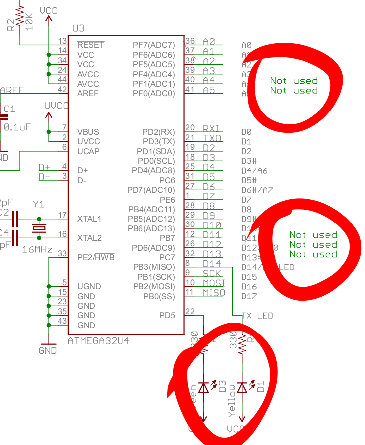
It turns out that Pro Micro doesn't break out all the pins. In fact, it only breaks out 18 GPIO pins, and uses 2 more for build-in LEDs, leaving the remaining 5 pins unconnected. Just take a look at the schematic:
OK, with some delicate soldering I can reclaim the two LED pins -- just remove the LEDs and solder wires in that place. That gives me 20 pins to work with. My keyboard has 88 keys. That means, that if I make a matrix 8×11, I can support them all with 19 pins, and even have one pin left for a LED or something. Yay. But 8×11 is not exactly how the keyboard looks physically -- it's more like 5.5×16 (some columns have 5 rows, some have 6). So, to get 8×11, I will have to transpose it and merge every two neighboring columns together. That's doable, it just means I will have fun time converting the layouts.
Now, let's look for some ready-to-use firmware, so that I don't have to do all this coding myself (not that it's very complicated, but I'm lazy). For that chip, this seems to be pretty popular: https://github.com/tmk/tmk_keyboard
First, I burned one of the example keyboards to the board with avrdude:
avrdude -p atmega32u4 -P /dev/ttyACM0 -c avr109 -U flash:w:gh60.hex(you have to get it into the boot mode first by pressing reset right when it boots).
Then I connected some of the switches to some of the column/row pins, and pressed them -- and voila, it typed some letters! So the firmware works great.
Next, I will have to modify it to support my particular keyboard layout, with this almost square matrix. Looking at the matrix.c file in the examples, you can see code like:
/* Row pin configuration
 * row: 0   1   2   3   4
 * pin: D0  D1  D2  D3  D5
 */
static void unselect_rows(void)
{
    // Hi-Z(DDR:0, PORT:0) to unselect
    DDRD  &= ~0b00101111;
    PORTD &= ~0b00101111;
}
Hmmm.... Does that mean I need to have all row pins on the same port? I need 8 rows, so that would be doable... Let's see... Nope. Whoever designed the Pro Micro, he or she left out a single pin from each port, so that no port has a complete set of pins broken out. Splendid. Let's look at the other examples...
OK, I can pretty much write anything I want in those functions, all I need is to initialize the pins I want and read them all into a single number with something like:
static uint8_t read_rows(void)
{
    return (PIND&(1<<0) ? (1<<0) : 0) |
           (PIND&(1<<1) ? (1<<1) : 0) |
           (PIND&(1<<2) ? (1<<2) : 0) |
           (PIND&(1<<3) ? (1<<3) : 0) |
           (PIND&(1<<5) ? (1<<4) : 0) |
           (PINB&(1<<7) ? (1<<5) : 0);
}
Not very pretty, I bet I could write it nicer, but that should work.OK, writing it all and writing the layout definition is going to take some time, but at least I know how to proceed. See you at the other end.
Discussions
Become a Hackaday.io Member
Create an account to leave a comment. Already have an account? Log In.