 zakqwy
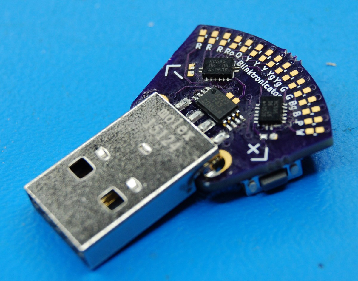
The boards arrived yesterday. They are, as expected, tiny.
They also have a number of issues, one of which is unfortunately fatal with respect to the #The Square Inch Project deadline: this generation will never work. But first, some pictures of a partially assembled and inadequately cleaned board:
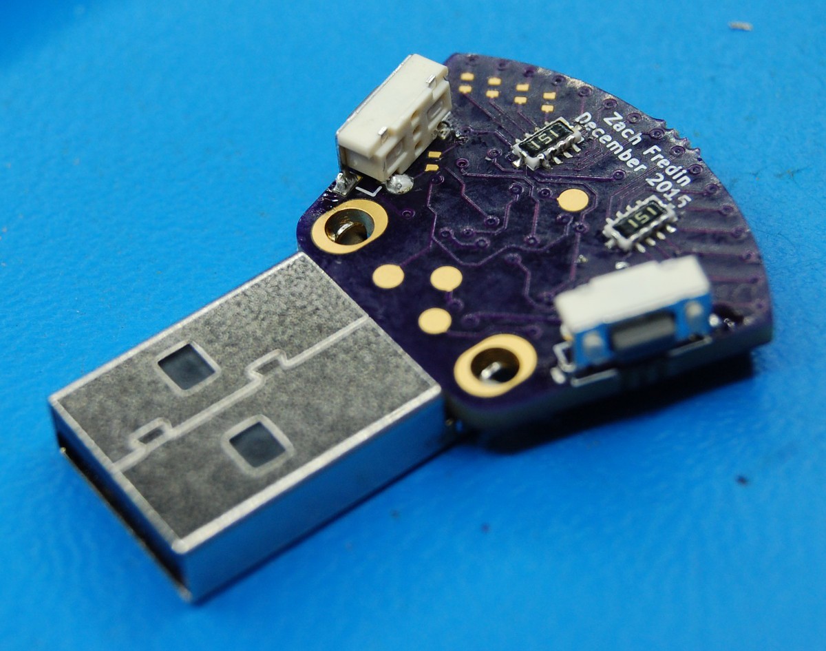
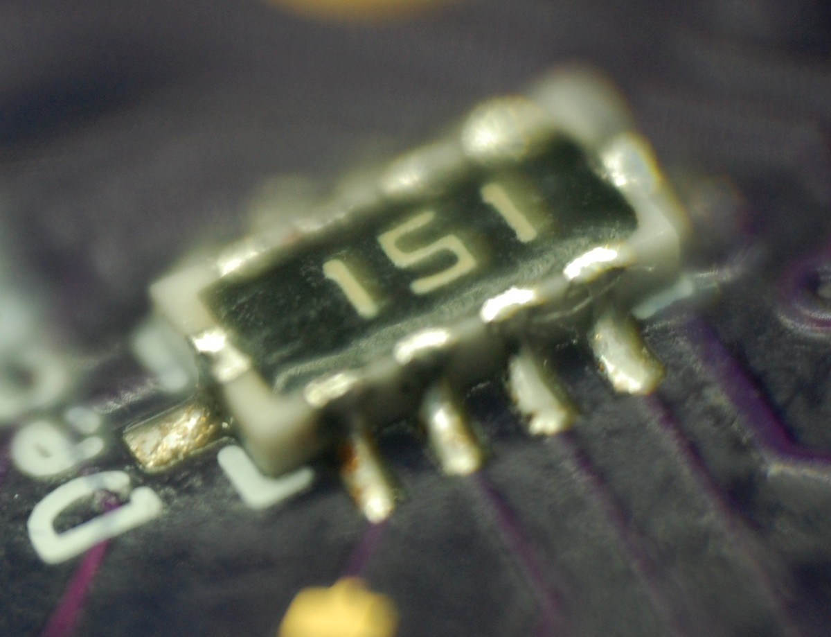
I'm particularly happy that the shift registers and the resistor networks appear to be successfully soldered to the board. Actually, that's one of the reasons I mostly finished this board after discovering the big problem--I wanted to make sure I'd be able to hand-solder the next generation if I used the same chip packages. These images are via 10x loupe (and thus have a hilariously bad depth of field), but the joints appear to be sound and un-bridged:

Above: 74HC595, DHVQFN16; below: 8-element 150-ohm resistor array, 1206. I lucked out in that the shift register doesn't require its bottom pad to be connected (or even grounded), so I skipped it entirely and didn't have to get out any reflow equipment. We'll see if that decision yields negative thermal consequences.
So what are the problems?
First: the USB connector footprint. The large (2.5mm!!) diameter holes used for the mounting tabs in place of slots mean only the corners of the tab are touching the plating, so I'm a bit concerned about the joint's mechanical strength. Worse, I completely forgot to include a pair of unplated holes for the plastic mounting bosses that protrude from the bottom of the plug, as shown in the center top image of the part drawing. Skipping these pins made initial alignment a bit more cumbersome, and I'm guessing they also add a bit of mechanical strength to the connection as well.
Second: the pogo pads for programming. I learned today while working on a concurrent project that these pads aren't large enough to use as bases for a pogo jig, and the 1.5mm diameter pad is tough to align with manually placed posts on blank FR-4. Might be worth skipping this entirely and just including a standard header.
Third, and most severe: the shift register footprints are flipped. As in, no matter how many times I rotate the chips, they're still mirror images of what I thought they would be. I even tried soldering one on upside down using tiny scraps of wire but I almost died of tedium. It just won't work.
What happened?
Well... I made my own footprints based on the datasheet. Er, that is to day, my erroneous interpretation of the datasheet. In the DHVQFN16 pinout drawing on page 20, I ignored the top image and based my pad design on the second image, which shows a view of the chip from the bottom. By copying this directly into copper instead of its mirror image, I doomed this generation before it ever hit the fab. Or at least, doomed it to a mediocre life of soldering practice.
What now?
I'll never make the 12/22/2015 deadline for an image of the working boards, so I'm going to accept a DQ in the contest. My missing (/forgot-to-order-last-week-so-I-ordered-them-Thursday) #NeuroBytes parts just showed up (as in, Saturday delivery, 20 minutes ago) and I want to see some blinky neurons on my desk before leaving for vacation on Tuesday. My hope is to have updated #RRRRoOYYYYgYgGGBgBPW Blinktronicator board designs off to fab before the holiday, in which case I'll get back to this project in early January.
Discussions
Become a Hackaday.io Member
Create an account to leave a comment. Already have an account? Log In.
Re: USB strength... why not just flood those holes with solder...? Am I missing something?
Are you sure? yes | no
Hot glue, bro
Are you sure? yes | no
LOL clearly I am missing something... low-temp rubber vs higher-temp metal?
Are you sure? yes | no