 zakqwy
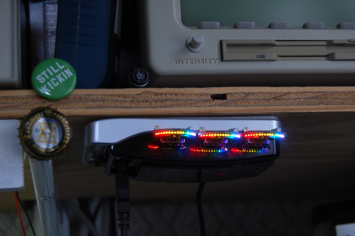
One thing I liked about the 2015 Hackaday Prize (specifically the Best Product competition) was that entrants had to make three identical working copies of a device. It's a good exercise, and it helps that OSHpark sells boards in multiples of three. Here they are, nestled together on my shelf-mounted USB hub:
The slots didn't work, which isn't entirely surprising. The browser preview showed off-center holes, so I wasn't shocked when I opened the package to find the same. A few minutes with a razor blade opened the holes up enough to stuff in the structural tabs from the USB plugs.
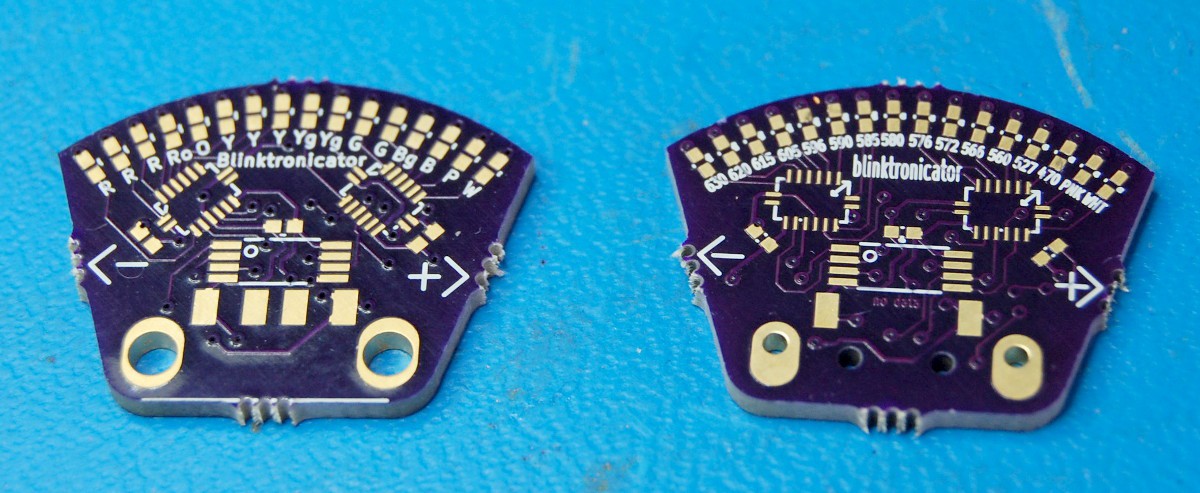
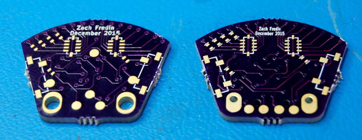
above and below: old (left) and new (right) board comparison, showing the "slots", lack of USB data pins, "no data" text on the front copper, revised programming pad locations, and a variety of other minor changes.
After assembling the first board, I used a few scraps of FR4 I had lying around along with a quartet of finicky surface-mount pogo pins to build a nifty little programming rig. The USB socket, salvaged from a still-in-use mini fan, is used for power/gnd and physical support; the entire structure is flexible enough that one can push down lightly on the board to engage the four pins.
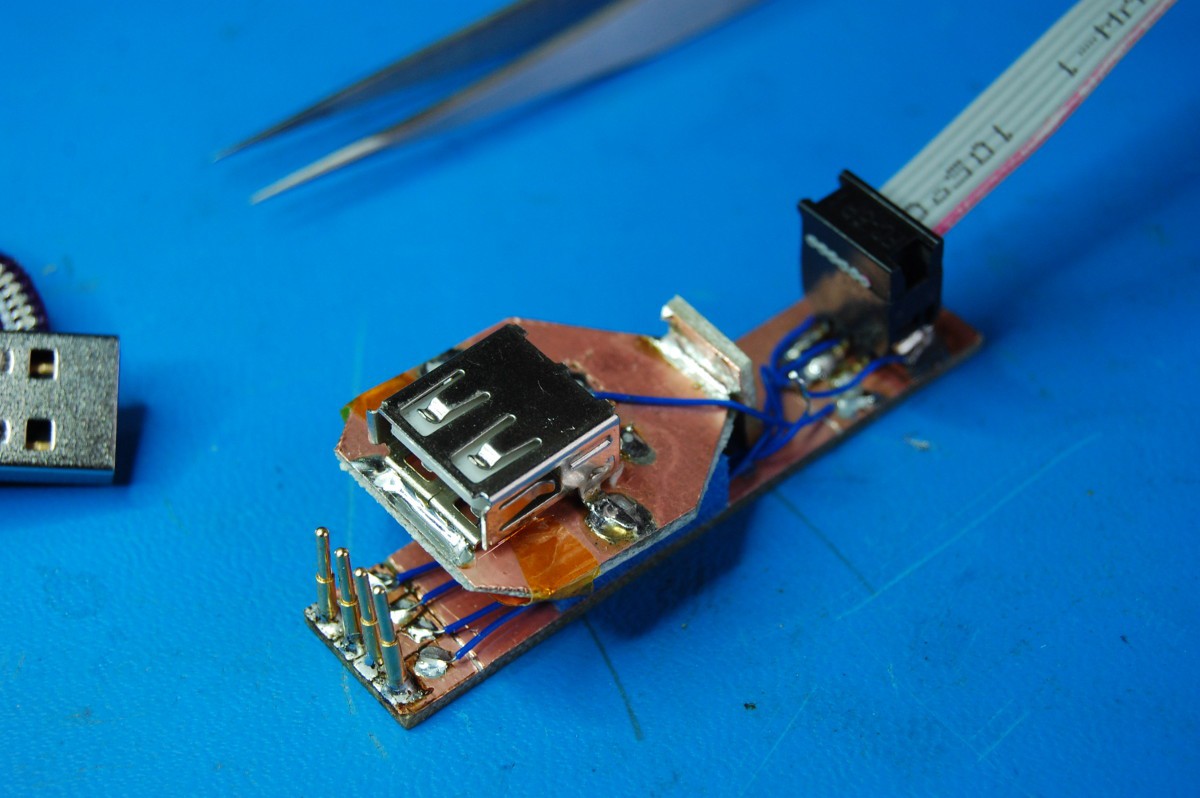
Not a terrific in-use picture, but you get the idea:

This was fun enough to build (and super convenient once complete) that I'm going to keep doing pogo rigs for my projects from here on out. However, the SMD spring pins can be a bit of a pain to properly align, so I'll likely start using traditional insertion devices instead.
One last thought: Dave Jones was right about soldering tips, folks. Get the damn chisel tip if your iron didn't come with it and throw out the conical garbage. I snapped a picture of my trusty WES51 posing with a finished board so you can see how much bigger the tip is compared to the 0.5mm pitch 16-DHVQFN shift registers; it's wide enough to span four pads:
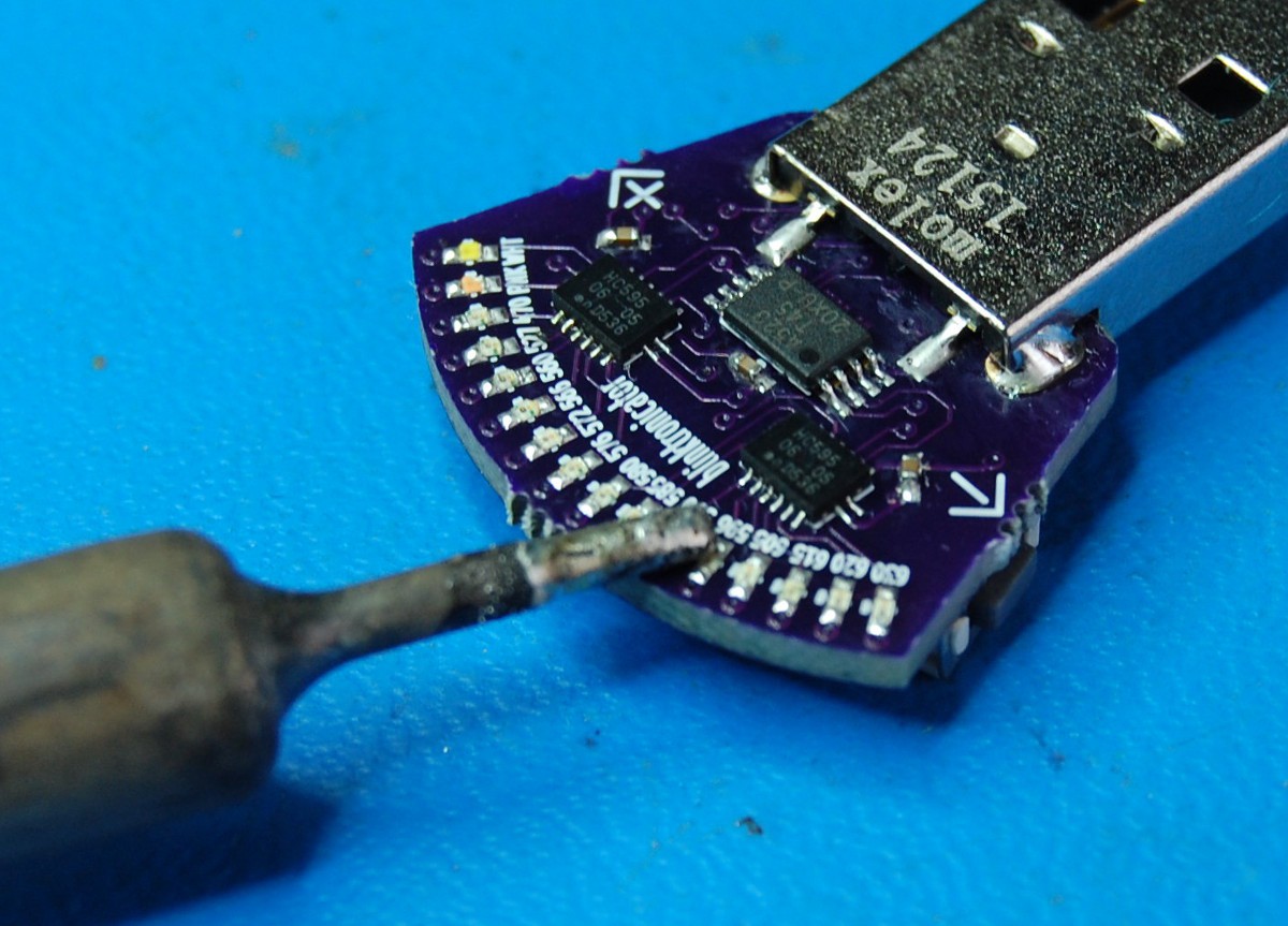
My process: 750 degree iron, Chip Quik 96.5Sn/3Ag/0.5Cu RoHS solder, and gobs of no-clean (hah!) gel flux. Tin the iron and drag it across the pins:

Super simple once the chips are properly aligned...
Discussions
Become a Hackaday.io Member
Create an account to leave a comment. Already have an account? Log In.
Beautiful. Is USB communication working yet? If so, I might need to get one of these ;)
(https://github.com/todbot/blink1/tree/master/hardware/firmware might be helpful!)
Are you sure? yes | no
Thanks! Unfortunately, USB comms probably won't be part of this project anytime soon; I'm more keen to get the firmware working well, as fading LEDs through shift registers is a fun challenge. After I'm satisfied with the code, I'll probably mark this as 'complete' and move on to the next thing--remember, my main purpose for the project was a quick LED wavelength reference.
@julien (who is hard to actually tag since there are a lot of 'juliens' on Hackaday) talked about forking the project and using V-USB to build a CPU gauge... I'm hoping something like that happens. MIT license... :-)
Are you sure? yes | no
That HUB full of blinktronicators looks gorgeous!
Are you sure? yes | no
Thanks! The LEDs are all on at ~80% duty cycle, so everything heats up a bit when they're left plugged in..
Are you sure? yes | no