 Eric Hertz
Update: EXCELLENT results briefly summarized at the bottom... (Update 2: and a couple more)
The "Groovy Circuit" of the last couple logs is now being tested with an abruptly-varying PWM signal...
0->3.3V PWM (20-80% duty cycle)
                V+
                ^
                |
                \
             R1 /
                \
                |
                +--|>|----.
                |         |
                |       __|__|
                |      | / \   3.3V
                |       /___\  Zener
                |         |
0->3.3V >---||--+--|<|----+----->  >----.
                |         |             | Audio
                \        ===            \ Amp
             R2 /         |             / Input
                \         V             \ ~30k
                |        GND            |
                V                       V
               GND                     GND
Again, the point of this circuit is several-fold.
First, it attempts to linearize the PWM signal, so the motor will be driven by an *analog* value rather than directly by PWM.
Second, it relocates that now-linearized signal such that at 50% PWM the input to the audio-amp is 0V, but at 20% PWM duty-cycle, the input to the audio-amp is now *negative* (without a negative power-supply available).
Third, it attempts to adjust *quickly* to sudden changes in the PWM value... E.G. If the motor's running forward at full-power (somewhere around 80% PWM), and suddenly the system needs to bring the motor to full-stop, the next PWM duty-cycle will be 50% (stop). Ideally, this circuit will respond to that sudden change.
I guess, in a sense, this circuit's output is similar to that of a D-to-A converter of the Resistor-Ladder sort (Thanks @Yann Guidon / YGDES, I get your reference, now), where the DtoA has both positive and negative power supplies. As opposed to, say, the output of an R/C filter...
R/C Filter "Averaging" circuit

0->3.3V PWM >---/\/\--+----->  >----.
                      |             |
                     ===            \ Amp
                      |             / Input
                      V             \ ~30k
                     GND            |
                                    V
                                   GND
An R/C filter wouldn't accomplish near-immediate response to sudden changes in PWM values... e.g. a sudden change, say, from 80% 50% and back to 80% in three cycles would result in almost zero change on the output, whereas the "groovy circuit" I came up with seems to respond almost immediately:
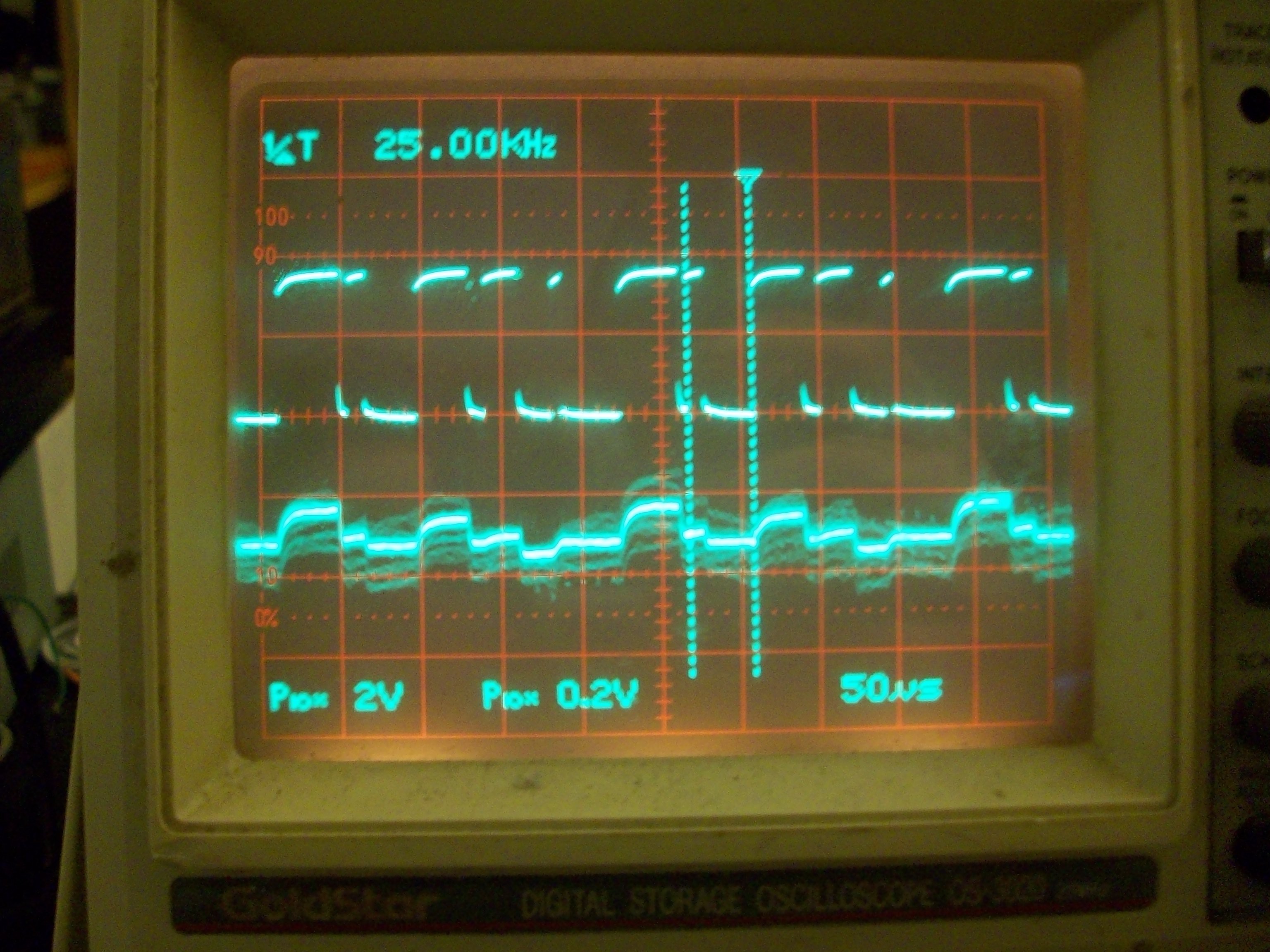
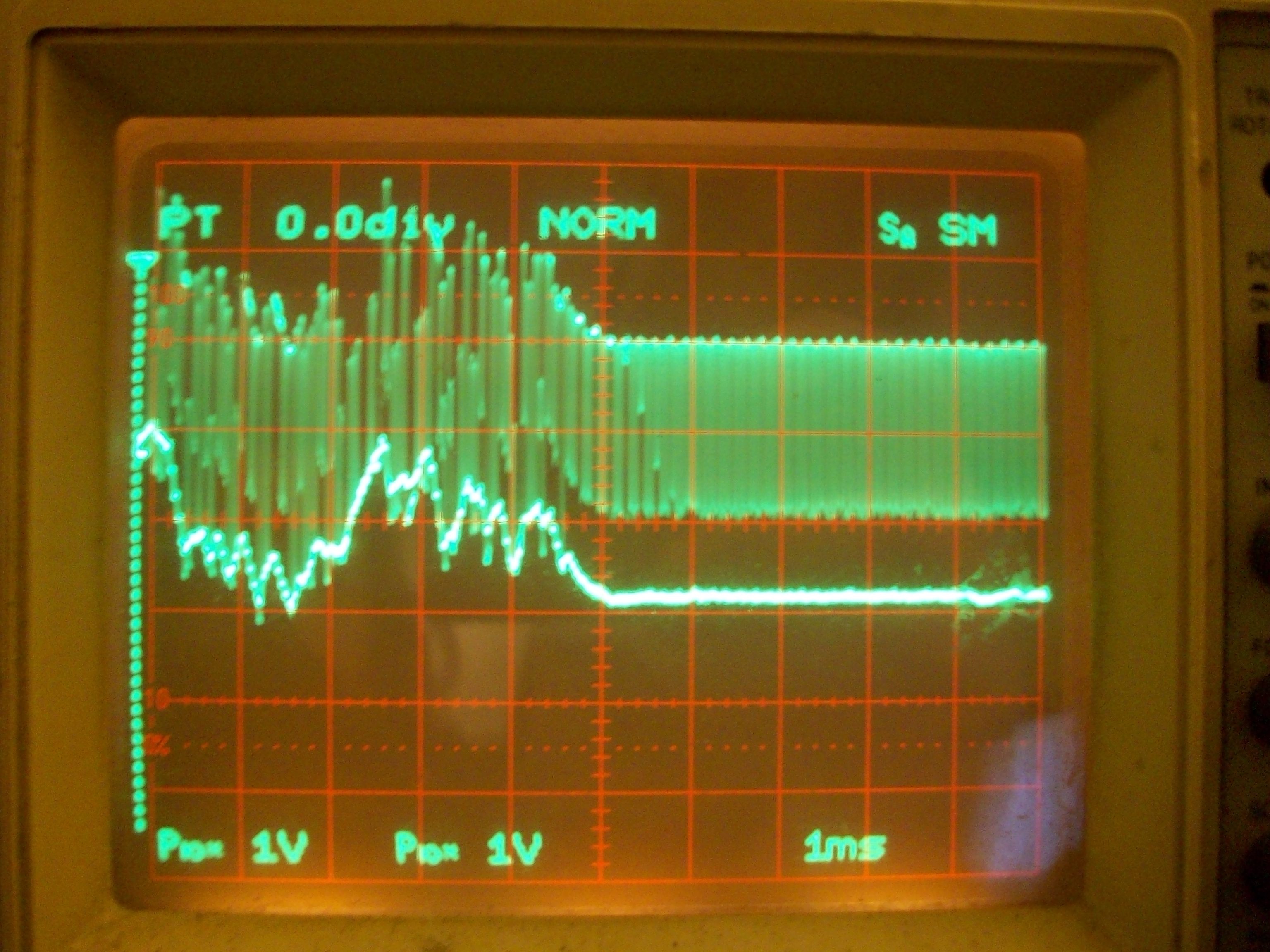
The first trace is the PWM input, varying dramatically in duty-cycle from cycle to cycle.
The second trace is the output of the "groovy circuit." I'm not yet sure where the noise is coming from, this is a *very* early experiment.
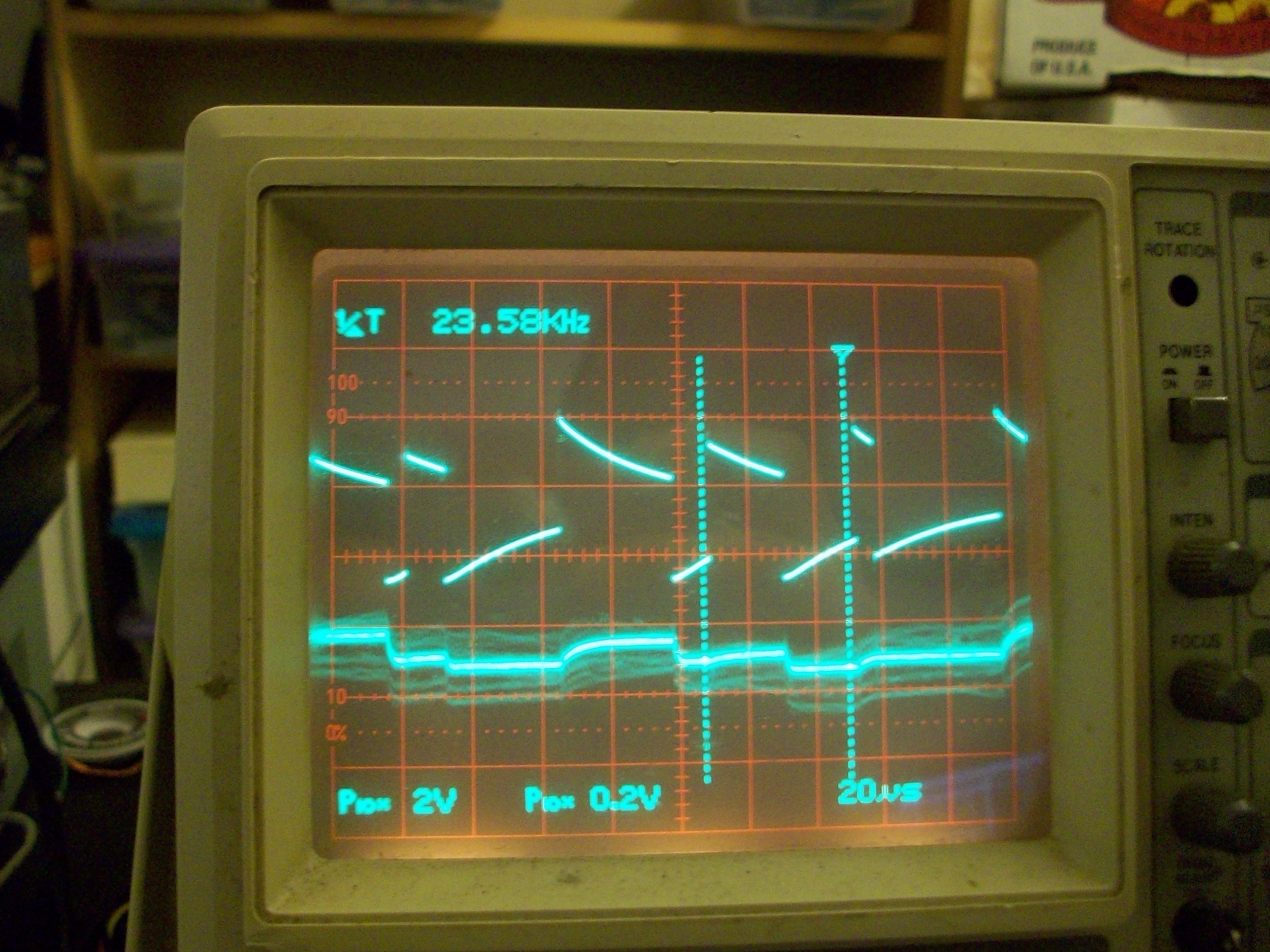
Here, the upper trace shows the output of the AC-coupling capacitor, before feeding into the diodes. You can see that the peaks and valleys vary in value from cycle to cycle, this variance is what determines the output voltage... A sort of dual-retriggerable peak detector circuit that relies heavily on the fact that the input voltage is always switching from 0V to 3.3V during each cycle.
Does it work *exactly* as I'd hoped...? Not sure, haven't done the full gamut of experiments yet. It definitely seems to work well with slowly-varying changes (as would an R/C filter, if I didn't need a negative output signal) (not shown here). Though, it looks like the output is scaled down a bit during these sudden-changes... something to ponder in later experiments.
-----------
Update:
Excellent results after swapping capacitors and changing some pots... *excellent*.
Video, maybe, soon.
Interesting side-effect I vaguely foresaw, but hadn't quite pinpointed... This circuit *inverts* the signal... E.G. 80% PWM is 3.3V for 80% of a cycle and 0V for 20%... So, an average of 80% of 3.3V, yet results in a *lower* voltage-output from the circuit... This would make sense... The average being .8*3.3 would be the "DC-offset" which is *removed* by the AC-coupling capacitor. The circuit output follows the *negative peak* of the AC-coupled signal, and since the DC offset increases with the PWM duty-cycle, and that DC-offset is *removed* by the AC-coupler, the negative peak goes *lower* as the PWM duty-cycle *increases*. Easily compensated-for in software, but an interesting side-effect.
Oddly, that's hard to see in the images above... The output voltage shown above seems in many cases to *follow* the positive duty-cycle. There's a lot at play in there... Of course we'll see *some* increase with the positive half of the duty-cycle (when the zener is on). The output of that circuit (with the old capacitor and pot values) was *way* off, 0.2V/div, while the 3.3V PWM signal varied dramatically in duty-cycle...
So, here's a snapshot of the *excellent* results with the new values:
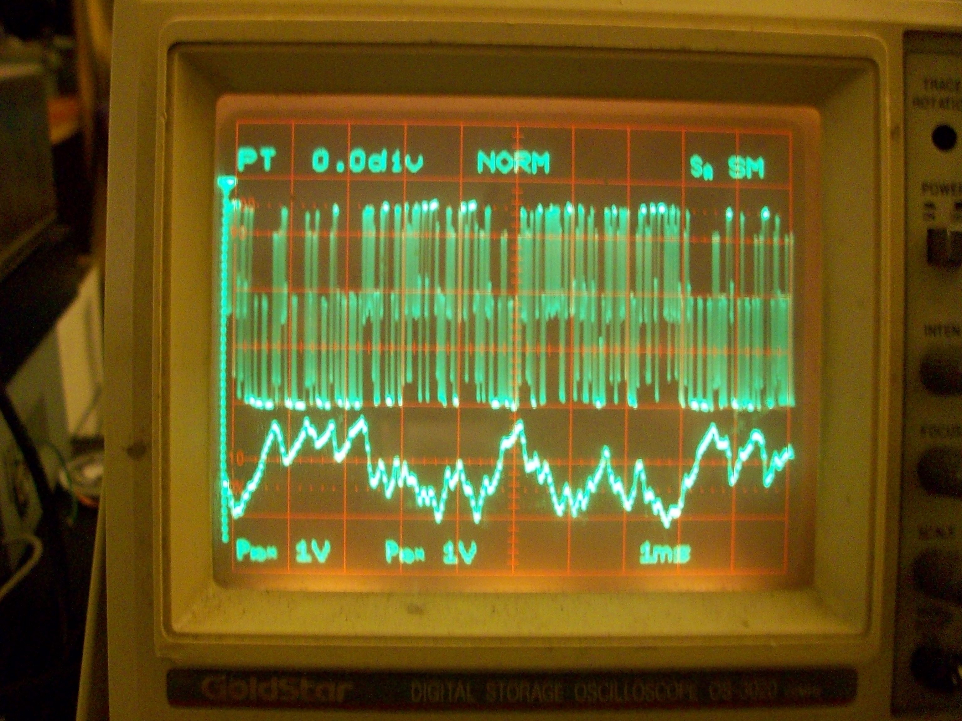
The upper trace being the PWM signal straight out of the microcontroller, the lower trace is the circuit's output. Note when the PWM duty-cycle is *low* for long-durations, the output voltage *increases*.
Here it is with the "top" trace after the AC coupling capacitor, and both signals centered with 0V at the center of the screen. Note how the output signal follows the bottom of the output, and goes both negative and positive. (Also note that it's about one diode-drop higher than the lower "peaks").
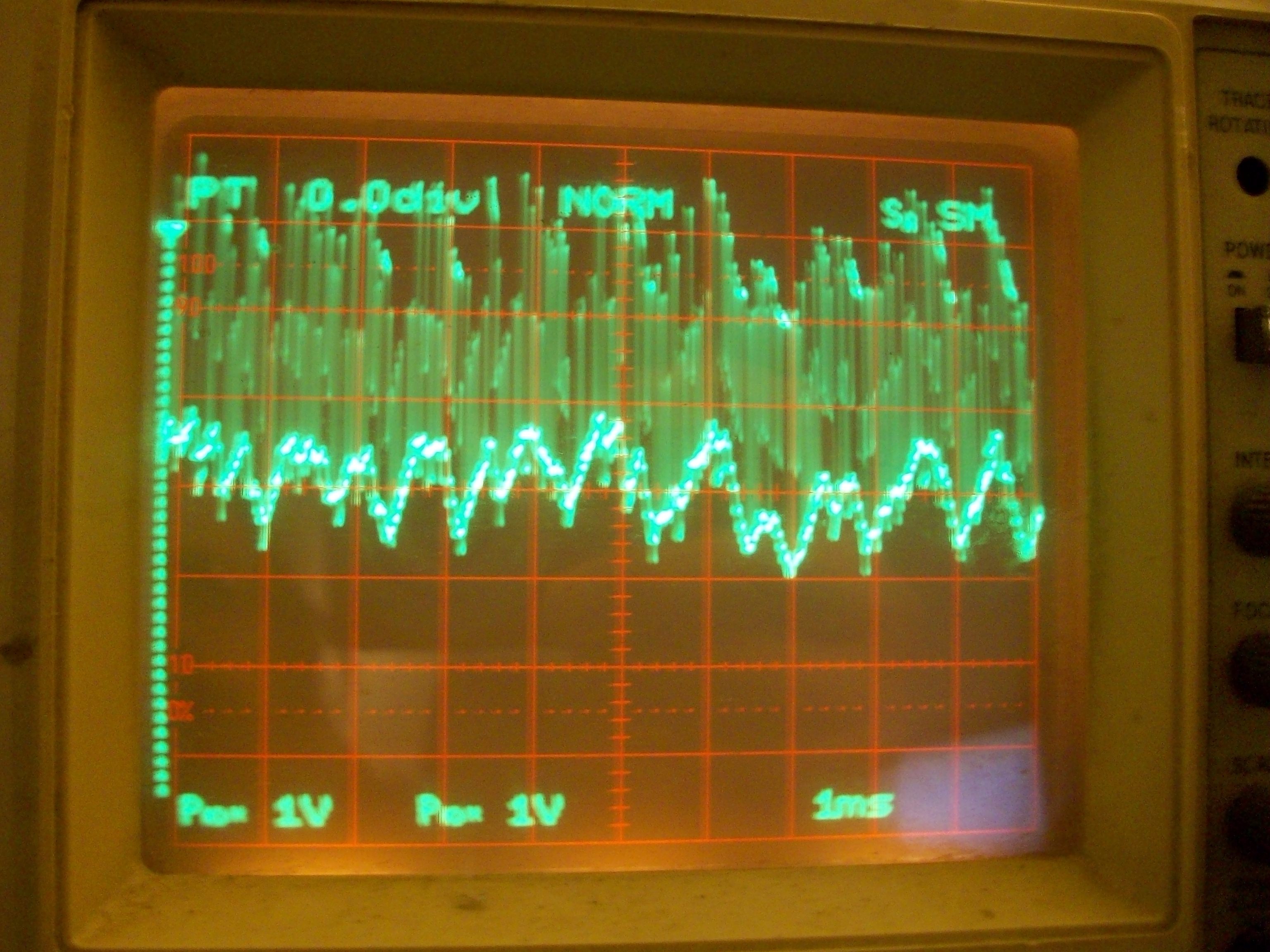
Again, the output signal is centered at 0V, so the signal swings from roughly -1V to +1V (again, without a negative power supply). And, *way more importantly* than its fast-response is that works great at constant PWM values.

E.G. the PWM in the above image is running at about 60%. (Obviously, due to the AC coupling, this fails when running at 0% and 100%.) The output of the circuit is a (roughly) constant *negative* 0.4V There is *slight* variance on the output as the diodes switch, a subtle triangular-wave on each PWM cycle, but I think that should be more than acceptable for driving a motor.
-----------
Update 2:
Ah hah... So there may be a distinct "R/C constant" going on here, still... making its output a bit more like a regular-ol' RC-filter than I expected... But not bad... and maybe adjustable and still functional...
Actually, not sure what I'm seeing, here... I think there's some aliasing to make things more confusing.
Discussions
Become a Hackaday.io Member
Create an account to leave a comment. Already have an account? Log In.