0%
0%
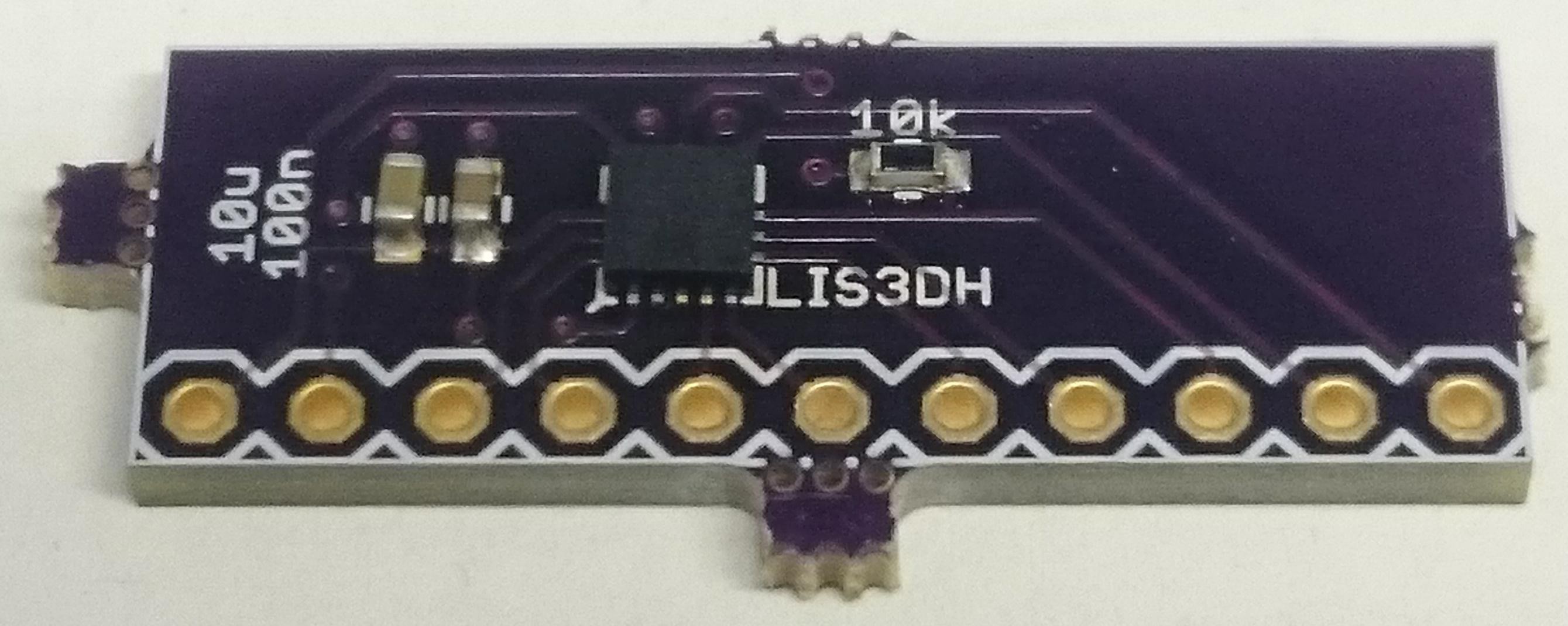
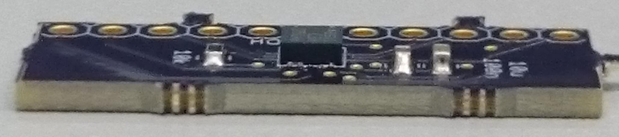
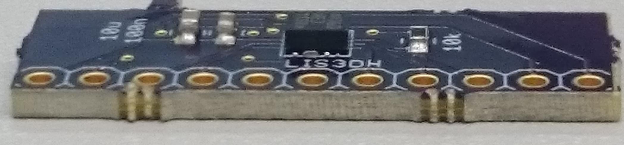
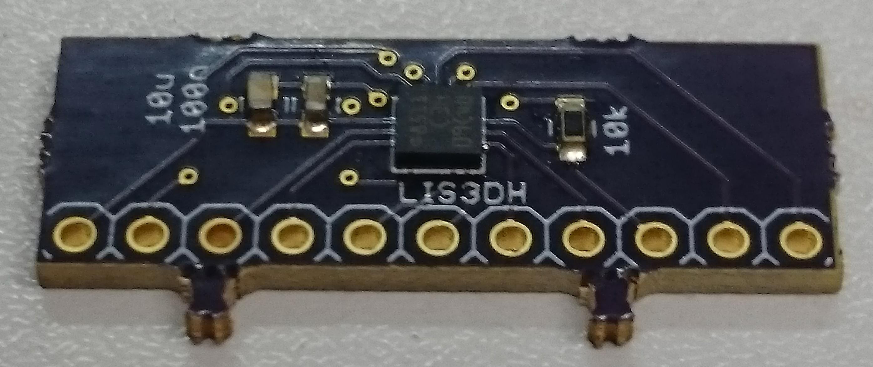
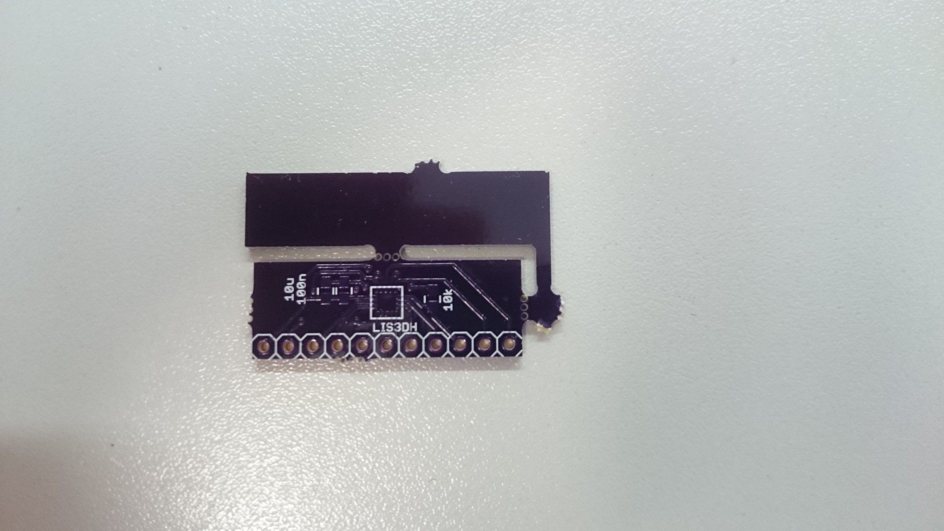
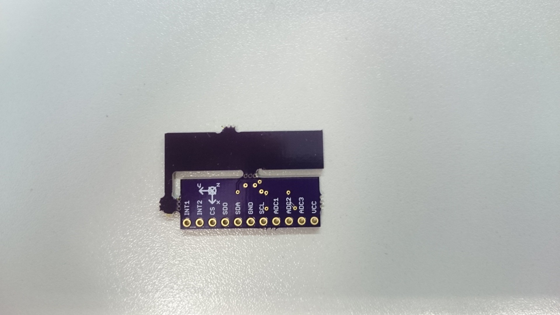
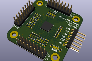
LIS3DH breakout board
3D accelerometer with SPI, I2C and 3 ADC inputs
 Christoph
Become a Hackaday.io member
Already have an account? Log in.
Just one more thing
To make the experience fit your profile, pick a username and tell us what interests you.
Pick an awesome username
hackaday.io/
Your profile's URL: hackaday.io/username. Max 25 alphanumeric characters.
Pick a few interests
Projects that share your interests
People that share your interests
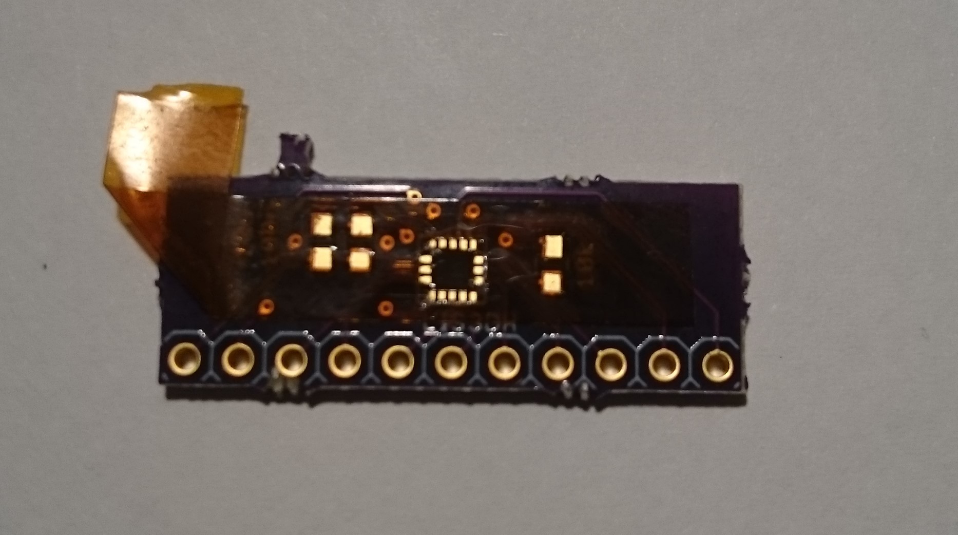
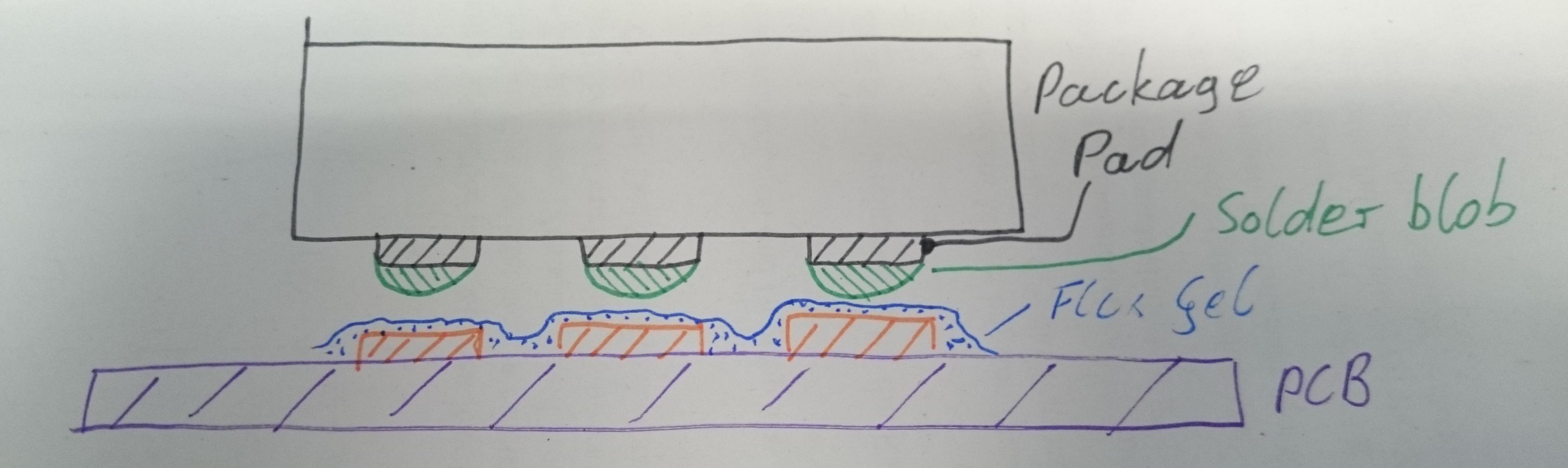 I was also advised to apply some solder to the PCB pads as well, but I didn't do that to avoid a "hill-on-hill" situation, which would make the part harder to place accurately (just my impression, I don't know if this is actually true):
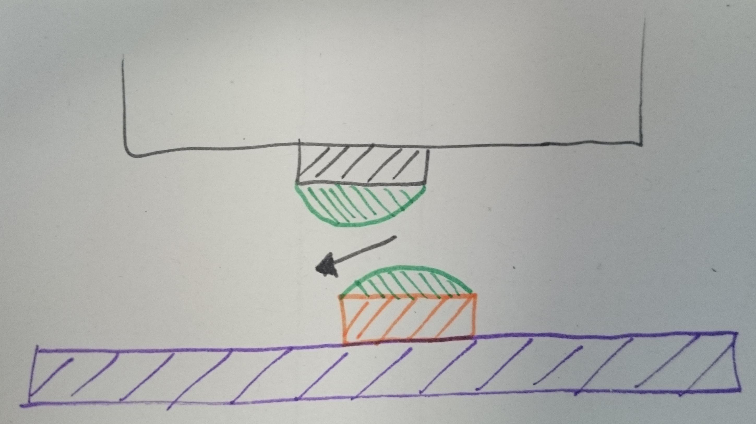

 T. B. Trzepacz
 facelessloser
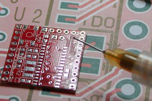
 arturo182
impressive project!