Close
0%
0%

Animatronic AVP Predator cannon

An animatronic display piece that is activated by an ultrasonic sensor

Similar projects worth following
An animatronic AVP Predator cannon senses when someone comes within three feet and is activated to perform a programmed sequence. An ultrasonic sensor triggers a Arduino to move the servos and activate the laser sight and LEDs in the cannon. The sound is handled by a Wave Shield. The cannon is cast resin and its movements are handled by two servos; one servo moves the sliding barrel housing and another geared servo raises and lowers the cannon into the firing position. This project was a collaboration with my friend Gary Jensen. Gary sculpted and cast the cannon and I created the animatronics. The cannon will eventually be placed in a desktop sarcophagus display for Gary's son.


Video of the finished animatronics-


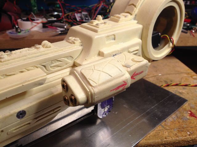
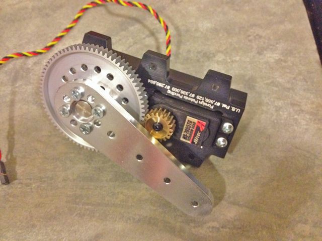
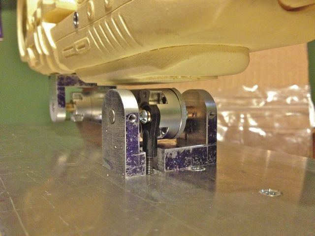
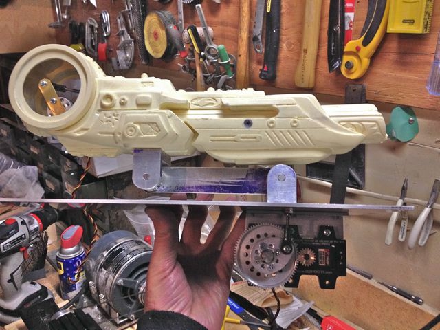
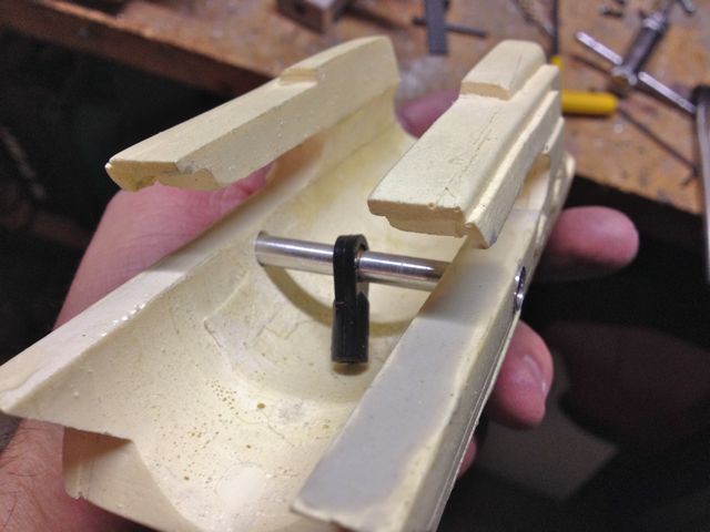
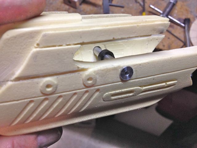
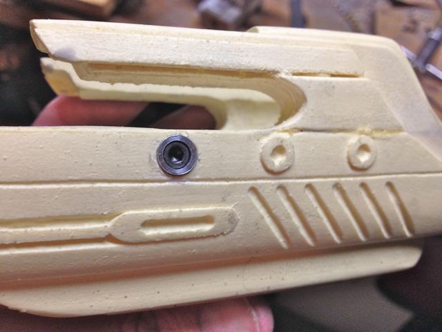
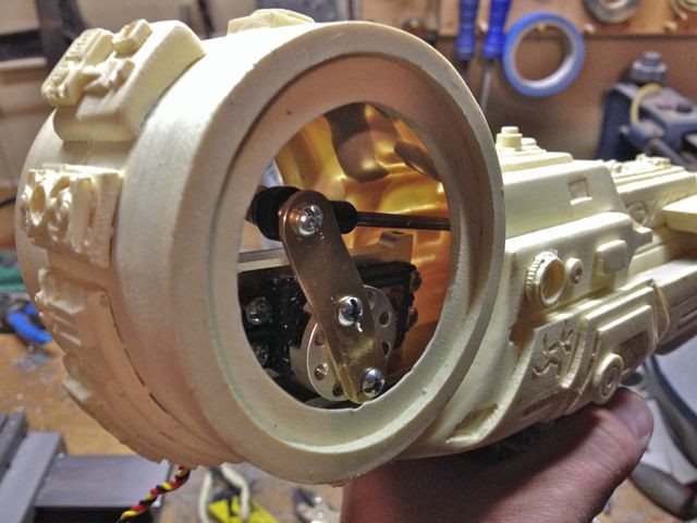
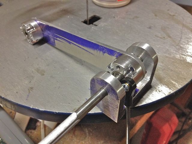
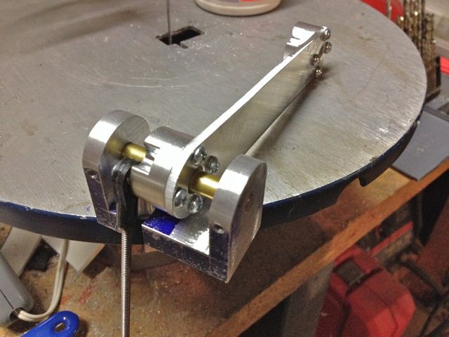
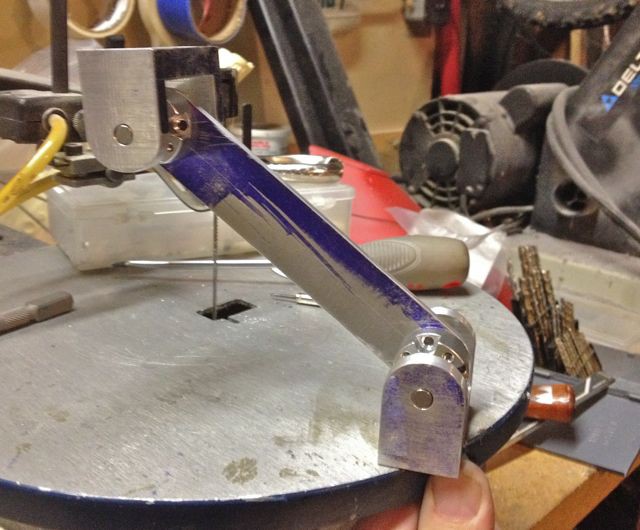
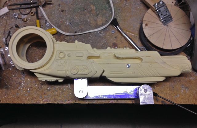
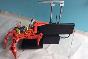
The chassis for this project was made entirely from Aluminum for durability. The arm uses a simple parallelogram mechanism in order to keep the cannon level as it raises up to the firing position and the arm end joints are supported by cartridge bearing assemblies. The leverage ratio is pretty high and the cannon is quite heavy with the installed servo hardware and wiring so I used a geared servo drive with a counter balance spring to control the arm movement. Since the Aluminum arm would eventually be covered by a detailed resin casting I had to make sure that all of the mechanics would be able to be hidden later.

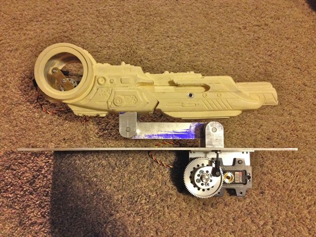
Both of the servos are high torque digital servos and I used a servo programmer to adjust the speed of the servos so the cannon movement during the recoil action matched that of the film and the arm would have a nice slow movement when raising and lowering.

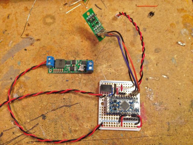
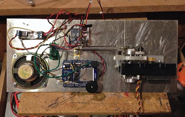
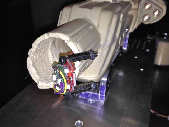
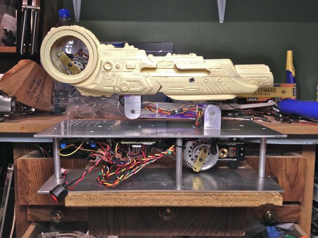
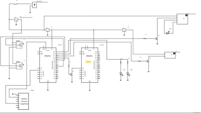
The two servos are controlled by an Arduino ProMini. The ProMini is soldered to a bread board PCB and power to the entire system is supplied by a 12V switching power supply. 12V is sent to the Buck Toot driver for the Luxeon LED and is also stepped down to 5V using a Pololu DC/DC converter which can output up to 7A to power the servos. A 5V @1A DC/DC regulator provides power to both of the Arduinos and WaveShield as well as the ultrasonic sensor and two blue SMT LEDs. The 5V output is stepped down to 3.3V using a voltage regulator to power the cannon laser sight.

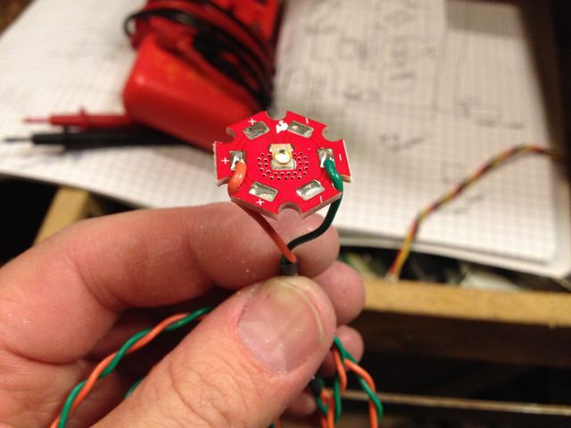
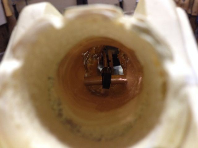
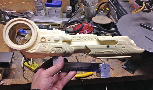
The two SMT blue LEDs in the end of the cannon light up during the power on sequence and the single blue Luxeon Rebel LED lights up when the cannon fires. The sound effects are handled by a Wave Shield. All of the LEDs, laser sight and sound are triggered using transistors. The sound files were created by me using several sound clips from the movies. It was a fair bit of work getting the movements, sound and LED timing just right!

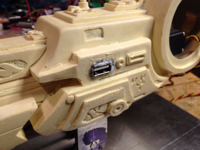
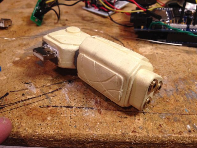
The laser sight is plugged into the side of the cannon using a USB connector so it can be easily removed for painting and shipping.

  • 1 × Arduino ProMini 5V This controls the servos, LEDs and triggers the sound effect
  • 1 × Arduino Pro 5V This sits under the Wave Shield
  • 1 × Adafruit Wave Shield This is used for the sound effects
  • 1 × Maxbotix LV-EZ1 ultrasonic range finder This is connected to the Arduino ProMini
  • 1 × Luxeon Rebel high power blue LED This provides the cannon firing light

View all 24 components

  • Build log 4- electronics

    jeromekelty04/19/2014 at 06:34 0 comments

    The electronics for this were pretty straightforward. The biggest issue with servo systems is to make sure the servos are powered from their own regulator- this will help isolate any electrical noise generated by the servos that would otherwise cause glitches in the servo movements. 

    Holes were drilled in the Aluminum base plate for the speaker and for running wires up the cannon arm. I decided to attach the laser sight pod to the cannon body using a USB port so it would be easy to detach it for painting and shipping. The female port was added to the cannon body using some ProPoxy20 epoxy putty and the same was done with the male end in the laser sight.

    The Luxeon LED was added to the inside of the cannon barrel using two standoffs and two SMT  LEDs were attached to the front of the Luxeon LED board. The wires for the LEDs and laser sight were then run along the inside of the cannon and they exited the canon just behind the upper arm end and then ran down the cannon arm. All of the electronics boards were then attached to the base plate using standoffs and a lower base plate was attached to the cannon base plate with three threaded Aluminum rods.

  • Build log 3- arm servo

    jeromekelty04/19/2014 at 05:58 0 comments

    To raise the arm I needed a very powerful servo so I used a geared servo drive to boost the servo's output torque. These servo drives use an external potentiometer attached to the output shaft drive gear for positional control. A thick Aluminum arm was modified and attached to the output shaft. The lower cannon arm end was then bolted to a large 1/8" thick Aluminum base plate and the geared servo drive was mounted underneath the base plate. The swivel link from the cannon arm was then attached to the servo output arm. 

    Later on during testing I found that while the cannon raised beautifully the weight of the cannon still caused it to drop too fast and it had a jerky motion to it that I didn't like. To solve this I added a brass arm to the servo output shaft and attached an extension spring to it to act as a counterbalance in order to reduce the load on the servo and smooth the lowering motion of the cannon.

  • Build log 2- recoil mechanism

    jeromekelty04/19/2014 at 05:10 0 comments

    The cannon has a sliding housing for the front of the barrel and there are slots cut in the barrel for a through bolt, which holds a 6-32 swivel link. Two machined Aluminum supports for the bolt were added to match the external appearance of the cannon and locate the bolt as it slides through the slot. A threaded rod connects the through bolt swivel link to a second link that is attached to the recoil servo arm. The servo has a high strength Aluminum hub and a brass arm is bolted to this. As the servo arm rotates the sliding housing moves forward and back.

  • Build log 1- arm construction

    jeromekelty04/19/2014 at 03:56 0 comments

    The arm is made from 1/8" thick Aluminum sheet and a bearing hub is fitted to each end of the arm. The arm end mounts are machined from 1" thick Aluminum plate and 1/4" diameter stainless steel rods are fitted as pivots for the arm bearings. The rods are held in place by 4-40 set screws in the arm end mounts. Spacers made from brass tubing keep the arm centered in the end mount. A 6-32 swivel link was attached to the lower bearing hub- this is what the geared servo pulls on in order to raise the arm. A notch was milled in the lower arm end mount to allow clearance for the pull rod and swivel link.

    There is a threaded rod on one side of the arm that is attached to each end mount with swivel links- this forms a parallel linkage that keeps the upper arm end mount level as the arm raises. The cannon has an Aluminum plate fitted to the inside bottom and the upper arm end mount is attached to the bottom of the cannon with two 6-32 bolts.

View all 4 project logs

  • 1
    Step 1

    Cannon code-


    #include "Servo.h" // include the servo library

    Servo armServo; // servo to raise the arm
    Servo cannonServo; // servo to recoil cannon

    // these constants won't change:

    const int triggerSensor = 1; // the sensor is connected to analog pin 1
    const int threshold = 36; // threshold value to decide when the sensor input triggers
    const int servoPin1 = 9; // control pin for arm servo
    const int servoPin2 = 6; // control pin for cannon servo
    const int lasersightPin = 11; // control pin for laser sight
    const int ledPin = 3; // control pin for cannon power up/down LED
    const int ledPin1 = 12; // control pin for cannon firing LED
    const int soundPin = 10; // control pin for sound board
    const int powerPin = 2;

    // these variables will change:
    int sensorReading = 0; // variable to store the value read from the sensor pin
    int ledState = LOW; // variable used to store the last LED status, to toggle the light

    void setup() {
    Serial.begin(9600); // use the serial port
    armServo.attach(servoPin1); // attaches the servo on pin 9 to the servo object
    cannonServo.attach(servoPin2); // attaches the servo on pin 6 to the servo object
    pinMode(lasersightPin, OUTPUT); // sets the laser sight pin as an output
    digitalWrite(lasersightPin, LOW); // turns off the laser sight pin
    pinMode(soundPin, OUTPUT); // sets the sound pin as output
    digitalWrite(soundPin, LOW); // turns off sound pin
    digitalWrite(ledPin1, OUTPUT); // sets cannon firing LED pin as output
    digitalWrite(ledPin1, LOW); // turns off the firing LED
    digitalWrite(powerPin, OUTPUT); // sets the servo power pin as output
    digitalWrite(powerPin, LOW); // turns off the servo power pin
    }

    void loop() {
    digitalWrite(powerPin, HIGH);
    armServo.write(100);
    cannonServo.write(63);

    // read the sensor and store it in the variable sensorReading:
    sensorReading = analogRead(triggerSensor);

    // if the sensor reading is less than the threshold:
    if (sensorReading <= threshold) {

    digitalWrite(soundPin, HIGH); // turn the sound on
    delay(10); // wait ten milliseconds
    digitalWrite(soundPin, LOW); // turn the sound off

    // fade in from min to max in increments of 1 point:
    for(int fadeValue = 0 ; fadeValue <= 255; fadeValue +=3) {
    // sets the value (range from 0 to 255):
    analogWrite(ledPin, fadeValue);
    // wait for 30 milliseconds to see the dimming effect
    delay(30);
    }
    delay(3000);
    digitalWrite(lasersightPin, HIGH); // turn on the laser sight
    armServo.write(50); // raise cannon arm
    cannonServo.write(125); // slide barrel forward
    delay(3000);
    digitalWrite(ledPin1, HIGH);
    cannonServo.write(63);
    delay(100);
    digitalWrite(ledPin1, LOW);
    delay(700);
    cannonServo.write(125);
    delay(3000);
    digitalWrite(ledPin1, HIGH);
    cannonServo.write(63);
    delay(100);
    digitalWrite(ledPin1, LOW);
    delay(700);
    cannonServo.write(125);
    delay(3000);
    digitalWrite(ledPin1, HIGH);
    cannonServo.write(63);
    delay(100);
    digitalWrite(ledPin1, LOW);
    delay(700);
    cannonServo.write(125);
    delay(3000);
    digitalWrite(lasersightPin, LOW);
    cannonServo.write(63);
    armServo.write(100);
    delay(3000);

    // fade out from max to min in increments of 1 point:
    for(int fadeValue = 255 ; fadeValue >= 0; fadeValue -=3) {
    // sets the value (range from 0 to 255):
    analogWrite(ledPin, fadeValue);
    // wait for 30 milliseconds to see the dimming effect
    delay(30);
    }
    digitalWrite(powerPin, LOW);
    }
    }

    WaveShield code (courtesy of Adafruit)-

    #include <FatReader.h>
    #include <SdReader.h>
    #include <avr/pgmspace.h>
    #include "WaveUtil.h"
    #include "WaveHC.h"


    SdReader card; // This object holds the information for the card
    FatVolume vol; // This holds the information for the partition on the card
    FatReader root; // This holds the information for the filesystem on the card
    FatReader f; // This holds the information for the file we're play

    WaveHC wave; // This is the only wave (audio) object, since we will only play one at a time

    #define DEBOUNCE 100 // button debouncer

    // this handy function will return the number of bytes currently free in RAM, great for debugging!
    int freeRam(void)
    {
    extern int __bss_end;
    extern int *__brkval;
    int free_memory;
    if((int)__brkval == 0) {
    free_memory = ((int)&free_memory) - ((int)&__bss_end);
    }
    else {
    free_memory = ((int)&free_memory) - ((int)__brkval);
    }
    return free_memory;
    }

    void sdErrorCheck(void)
    {
    if (!card.errorCode()) return;
    putstring("\n\rSD I/O error: ");
    Serial.print(card.errorCode(), HEX);
    putstring(", ");
    Serial.println(card.errorData(), HEX);
    while(1);
    }

    void setup() {
    // set up serial port
    Serial.begin(9600);
    putstring_nl("WaveHC with 6 buttons");

    putstring("Free RAM: "); // This can help with debugging, running out of RAM is bad
    Serial.println(freeRam()); // if this is under 150 bytes it may spell trouble!

    // Set the output pins for the DAC control. This pins are defined in the library
    pinMode(2, OUTPUT);
    pinMode(3, OUTPUT);
    pinMode(4, OUTPUT);
    pinMode(5, OUTPUT);

    // pin13 LED
    pinMode(13, OUTPUT);

    // enable pull-up resistors on switch pins (analog inputs)
    digitalWrite(14, HIGH);
    digitalWrite(15, HIGH);
    digitalWrite(16, HIGH);
    digitalWrite(17, HIGH);
    digitalWrite(18, HIGH);
    digitalWrite(19, HIGH);

    // if (!card.init(true)) { //play with 4 MHz spi if 8MHz isn't working for you
    if (!card.init()) { //play with 8 MHz spi (default faster!)
    putstring_nl("Card init. failed!"); // Something went wrong, lets print out why
    sdErrorCheck();
    while(1); // then 'halt' - do nothing!
    }

    // enable optimize read - some cards may timeout. Disable if you're having problems
    card.partialBlockRead(true);

    // Now we will look for a FAT partition!
    uint8_t part;
    for (part = 0; part < 5; part++) { // we have up to 5 slots to look in
    if (vol.init(card, part))
    break; // we found one, lets bail
    }
    if (part == 5) { // if we ended up not finding one :(
    putstring_nl("No valid FAT partition!");
    sdErrorCheck(); // Something went wrong, lets print out why
    while(1); // then 'halt' - do nothing!
    }

    // Lets tell the user about what we found
    putstring("Using partition ");
    Serial.print(part, DEC);
    putstring(", type is FAT");
    Serial.println(vol.fatType(),DEC); // FAT16 or FAT32?

    // Try to open the root directory
    if (!root.openRoot(vol)) {
    putstring_nl("Can't open root dir!"); // Something went wrong,
    while(1); // then 'halt' - do nothing!
    }

    // Whew! We got past the tough parts.
    putstring_nl("Ready!");
    }

    void loop() {
    //putstring("."); // uncomment this to see if the loop isnt running
    switch (check_switches()) {
    case 1:
    playcomplete("SOUND1.WAV");
    break;
    case 2:
    playcomplete("SOUND2.WAV");
    break;
    case 3:
    playcomplete("SOUND3.WAV");
    break;
    case 4:
    playcomplete("SOUND4.WAV");
    break;
    case 5:
    playcomplete("SOUND5.WAV");
    break;
    case 6:
    playcomplete("SOUND6.WAV");
    }
    }

    byte check_switches()
    {
    static byte previous[6];
    static long time[6];
    byte reading;
    byte pressed;
    byte index;
    pressed = 0;

    for (byte index = 0; index < 6; ++index) {
    reading = digitalRead(14 + index);
    if (reading == LOW && previous[index] == HIGH && millis() - time[index] > DEBOUNCE)
    {
    // switch pressed
    time[index] = millis();
    pressed = index + 1;
    break;
    }
    previous[index] = reading;
    }
    // return switch number (1 - 6)
    return (pressed);
    }


    // Plays a full file from beginning to end with no pause.
    void playcomplete(char *name) {
    // call our helper to find and play this name
    playfile(name);
    while (wave.isplaying) {
    // do nothing while its playing
    }
    // now its done playing
    }

    void playfile(char *name) {
    // see if the wave object is currently doing something
    if (wave.isplaying) {// already playing something, so stop it!
    wave.stop(); // stop it
    }
    // look in the root directory and open the file
    if (!f.open(root, name)) {
    putstring("Couldn't open file "); Serial.print(name); return;
    }
    // OK read the file and turn it into a wave object
    if (!wave.create(f)) {
    putstring_nl("Not a valid WAV"); return;
    }

    // ok time to play! start playback
    wave.play();
    }


  • 2
    Step 2

    Cannon electrical schematic

    Larger version here-

View all instructions

Enjoy this project?

Share

Discussions

Similar Projects

Does this project spark your interest?

Become a member to follow this project and never miss any updates