0%
0%
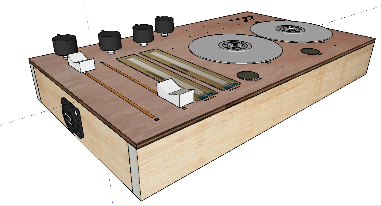
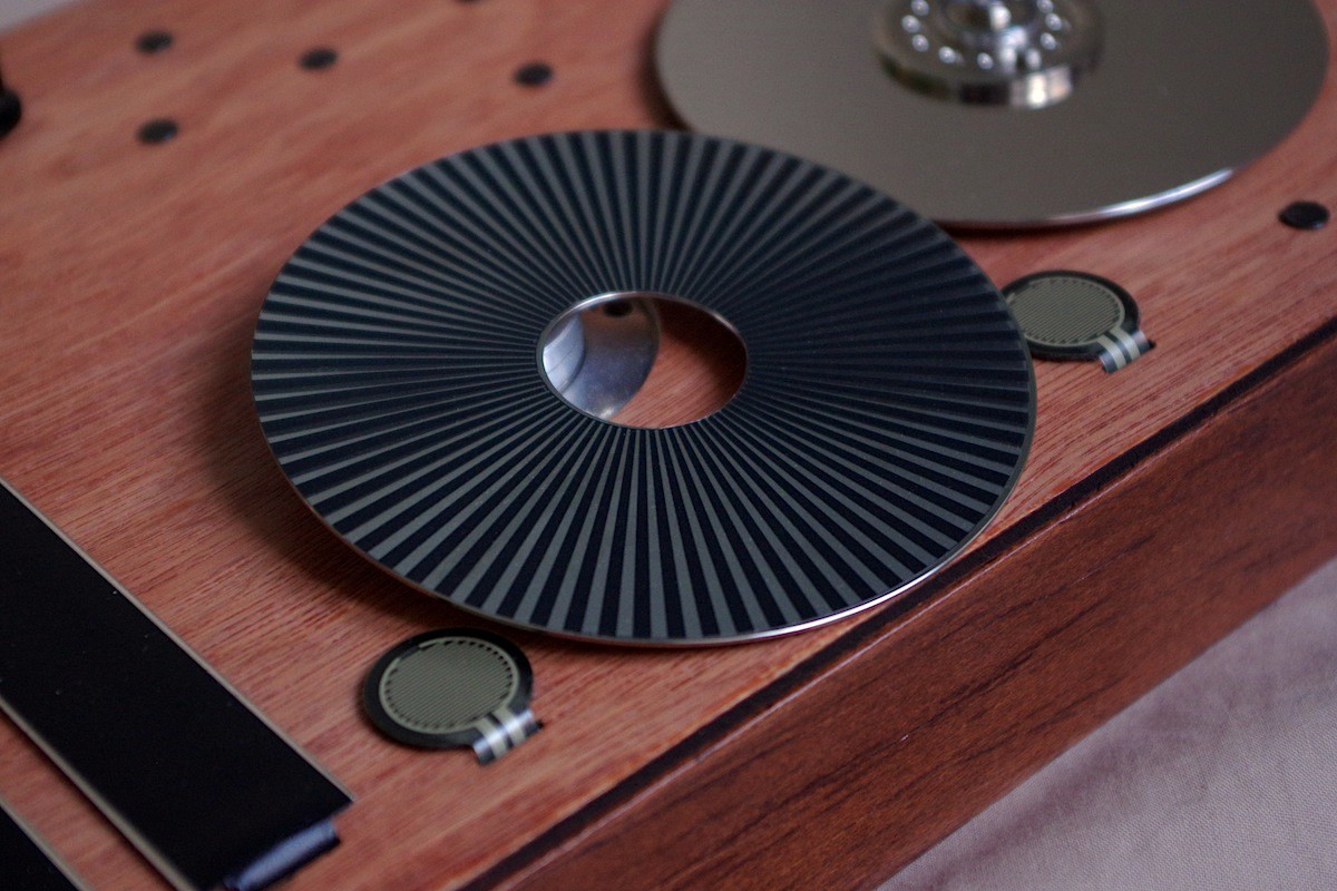
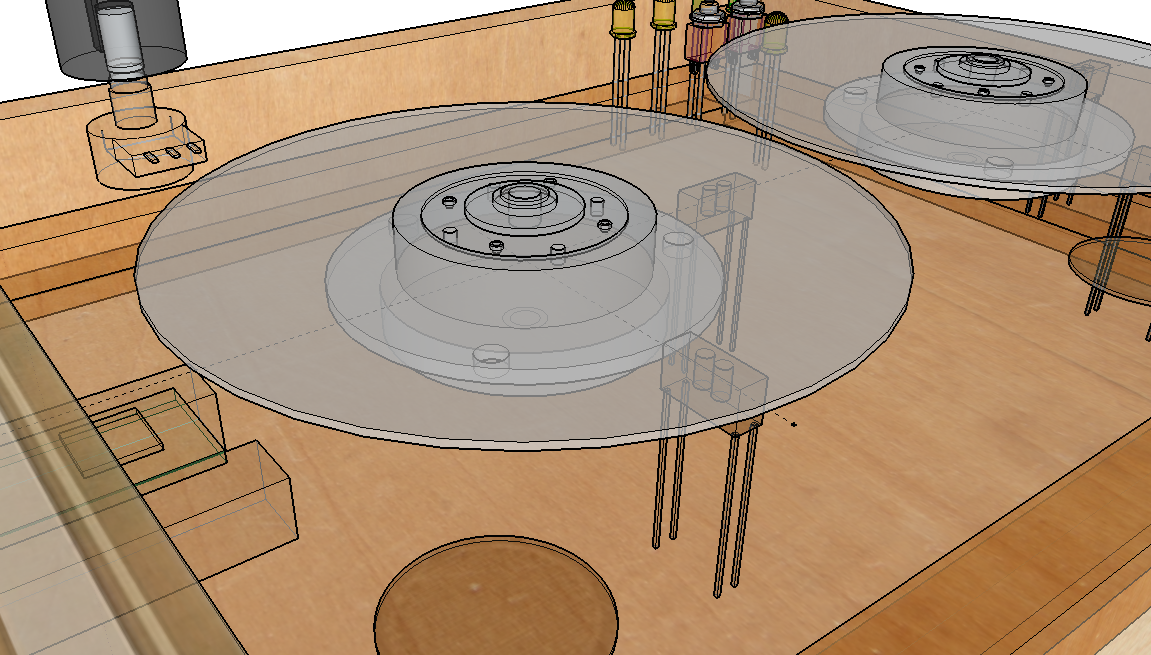
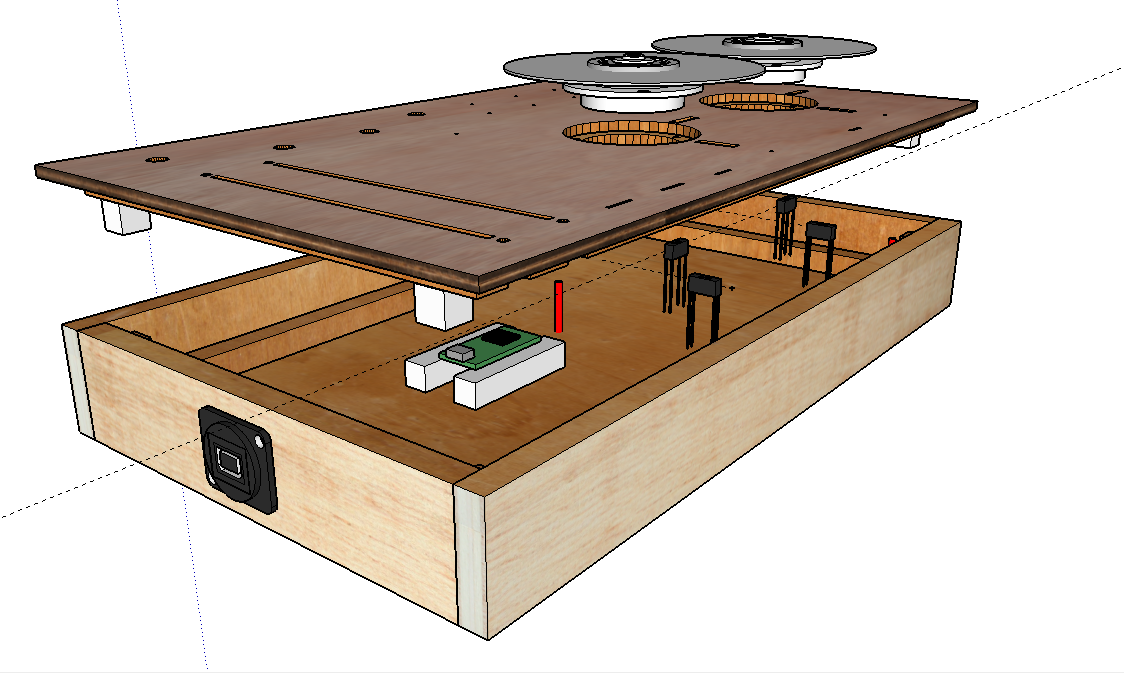
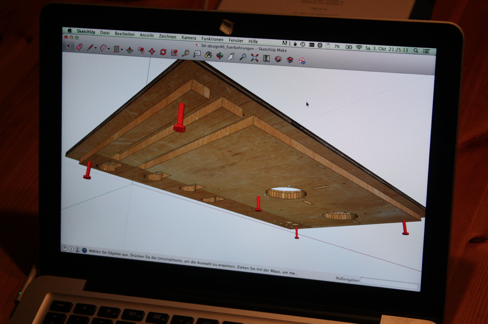
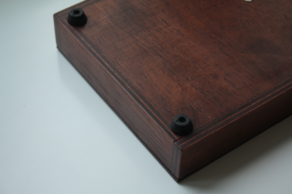
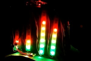
Wooden sensor box w/ 2 rotary disks
A homebuilt wooden sensor box i made, mainly for controlling PureData.
 Jan Godde
Become a Hackaday.io member
Already have an account? Log in.
Just one more thing
To make the experience fit your profile, pick a username and tell us what interests you.
Pick an awesome username
hackaday.io/
Your profile's URL: hackaday.io/username. Max 25 alphanumeric characters.
Pick a few interests
Projects that share your interests
People that share your interests


 AndyMac
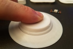
 Daren Schwenke
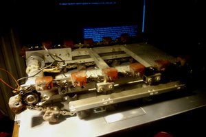
 PJK
PJK
I'm looking to add some extra expressiveness to my electronic drum set. I'd like to add semi-circular shaped ribbon controllers underneath the cymbals or maybe an XY pad. And some sort of IR sensor underneath the mesh drum heads, so that pushing down on them sends a MIDI CC #. Could all of these extra controllers be wired into standard cable type connectors to all go to a central "brain" type module that would house the Teensy board?