Josh
JoshBuild Details
This will also double as the instructions, separated into 2 parts, one for making the burned letters, and one for the night light electronics.
For the sign:
You need:
- Slices of logs: They should be about an inch thick, but quality of cut does not matter. Mine were about 8" pieces chain-saw cut without finishing.
- Metal foil tape: I got the cheapest foil tape I could find at Home Depot. It should be foil and adhesive, no paper or foam.
- Stencils: I used some stencils about 2" high. They do not need to be the full size of the wood because you will enlarge the letters.
- Pen or marker
- Exact-o knife
- Stuff to accomplish enlarging (see method below)
- Low heat torch: I used an oxy-acetylene with a very tiny tip. I think propane would work fine.
Test the tape
In the image above I made a T at first, but I think making a gap would be better as it is closer to how the letters will be formed. Get a scrap piece of wood and place 3 layers of tape midway across. Leave a 1/2" gap and place another 3 layers of tape. Make sure to line the layers perfectly or trim them with an exact-o knife so that any wood showing is bordered with no less than 3 layers of tape.
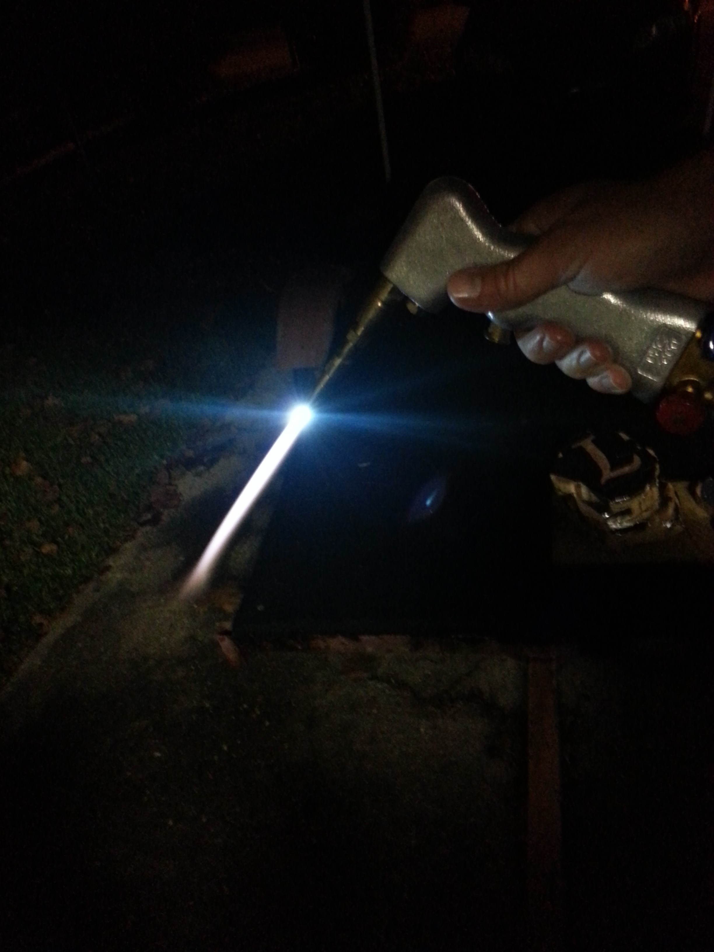
Go outside and fire up your torch. Take the taped wood and place it on an object that won't reasonably be harmed with the torch, like a metal table. A grill may work. I used a trailer fender. Use the torch sparingly to char the wood by quickly "brushing" the flame on to the exposed wood for less than a second, and removing. Wait several seconds for the wood and tape to cool. Try to singe the exposed wood without damaging the tape as much as possible. You DO NOT need to make the wood black, just darken it up.
Remove the tape and observe the results.
I first tried with 1 layer of tape and found that the heat permanently bonded the tape glue to the wood. I then used 3 layers, and was able to get a good darkening of the wood without the bottom layer of glue bonding to the wood.
If 3 layers of tape still presents issues with the glue bonding to the wood, try more layers, less flame exposure, or different tape. If you can't get your test piece to work, STOP NOW.
Build the stencil enlarger
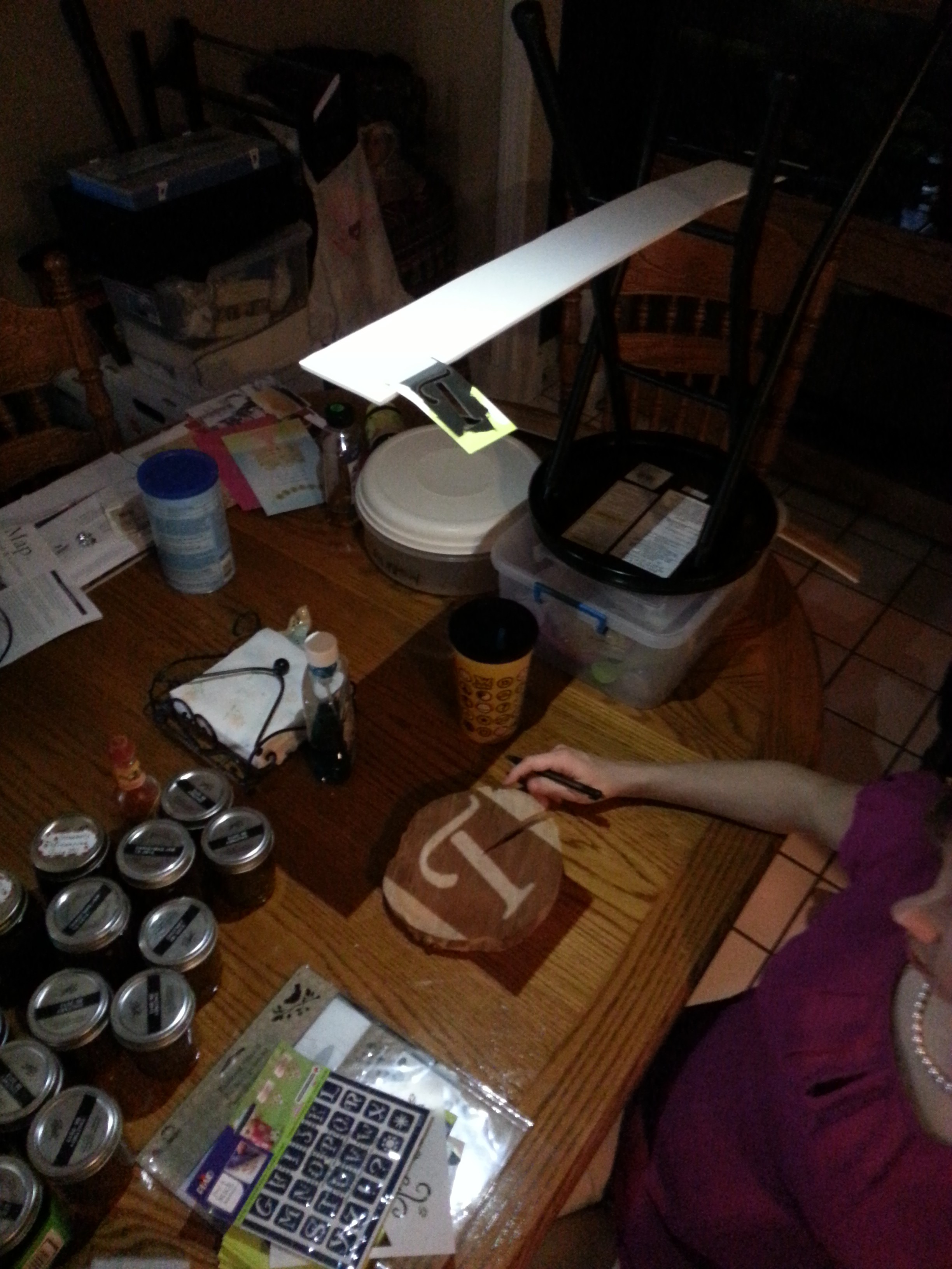
To build an enlarger, you simply need a way to hold your cellphone flashlight about 4' above a table pointing down, and suspend the stencil under the light so that the light shines through the stencil and allows you to trace the stencil on to the wood piece. I was able to balance my cellphone on my dining room chandelier pointing down. To support the stencil I turned a kitchen stool upside down and placed a yard stick on the foot rungs such that it cantilevered out over the table. I then taped the stencil to the edge of the yard stick and moved it under the cellphone light. To change the size of the letters projected on to the wood, move the wood closer or further away from the stencil, or move the stencil closer or further from the light. A cellphone light is required because it acts like a point light, where any flashlight will have a reflector that will make the letter fuzzy in the projection. You could also rig up a single led if you have the ability.
Letter the wood
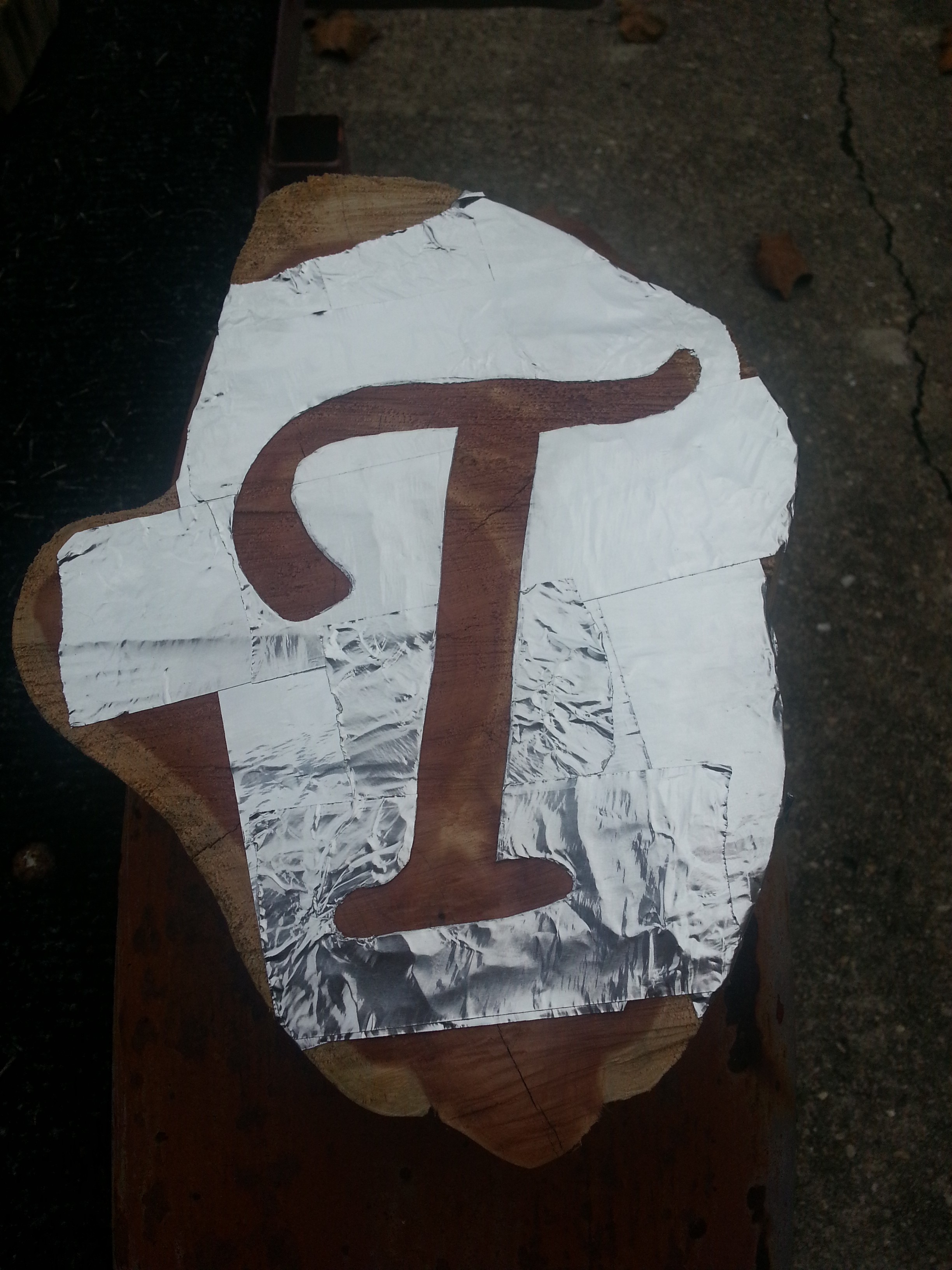
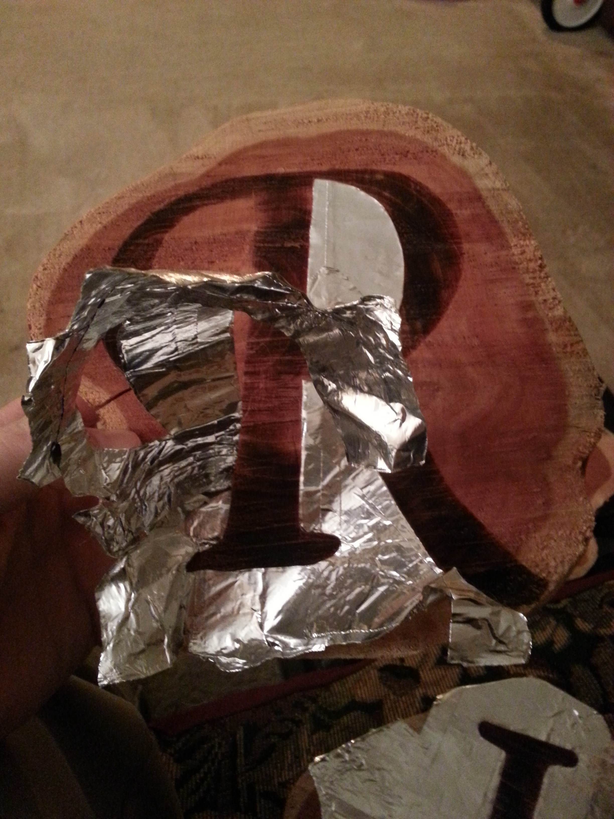
Place 3 layers of tape covering the majority of the wood where you are going to burn it. Place your wood under your stencil projector and trace the shape of your letter. Once all letters are traced, use your exact-o knife to cut out the letters. Be sure there is no glue and that the edges are crisp and 3 layers thick. Any trace of tape 1 or 2 layers thick may bond to the wood when hit with the torch.
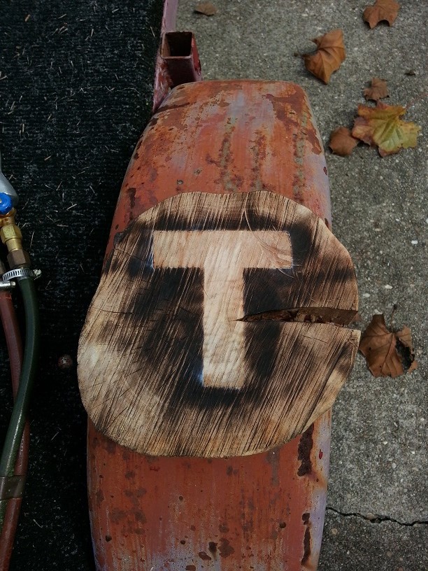
Burn the wood
Using the torch technique that worked best for you in the "Test the tape" section, slowly trace the exposed wood with the flame to sing and darken it. Be careful not to expose the tape to continuous heat or the glue will bond to the wood. In my practice, I could trace small portions of the letters for about 1 second, then pull the flame away and it worked well. I spent about a minute burning each letter, even though I was taking my time. Aiming the flame more toward the edges of the letters rather than the center will help to give better contrast. I aimed more to the center and some of my letters faded too much at the edge.
Remove the tape
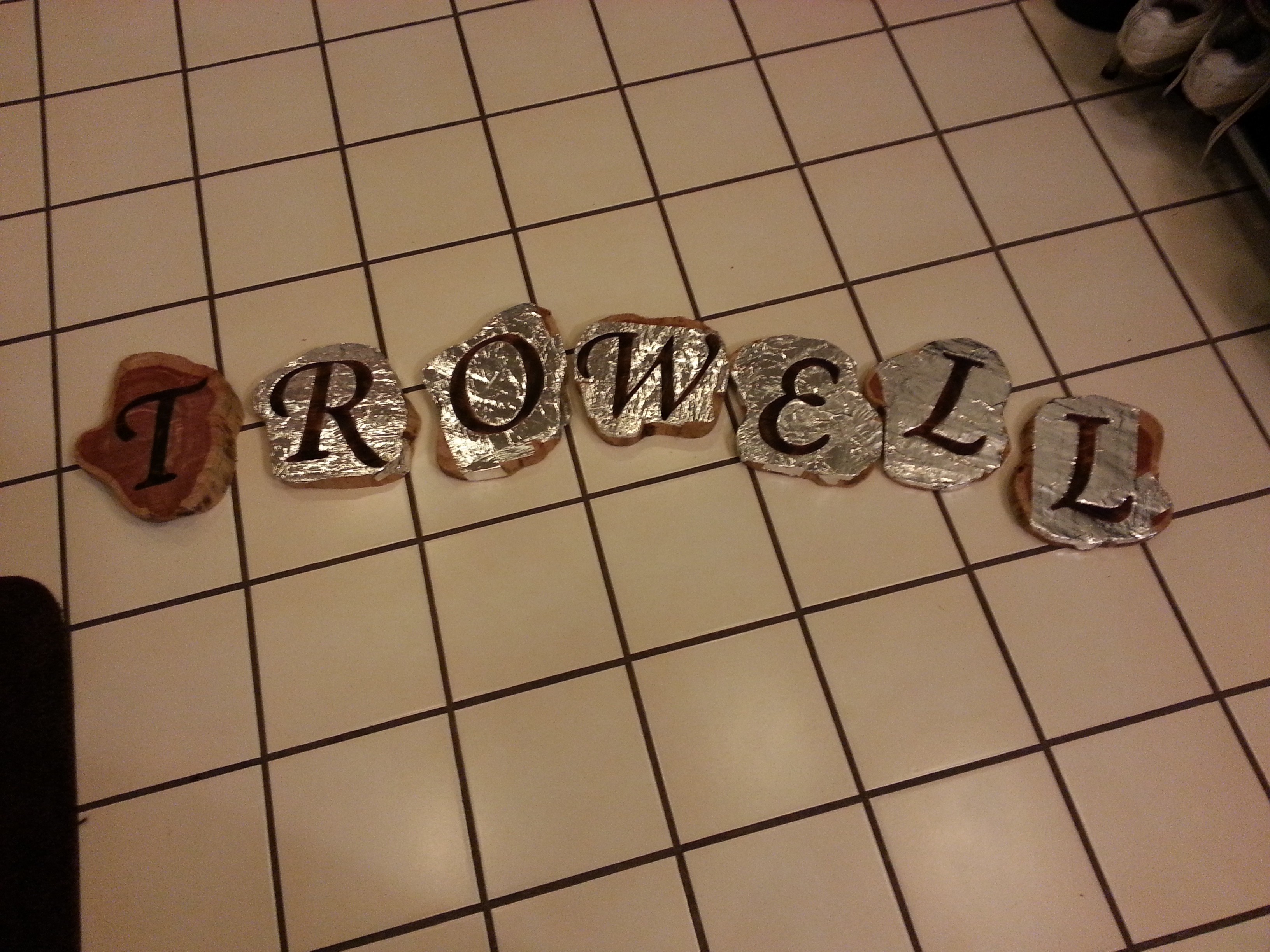
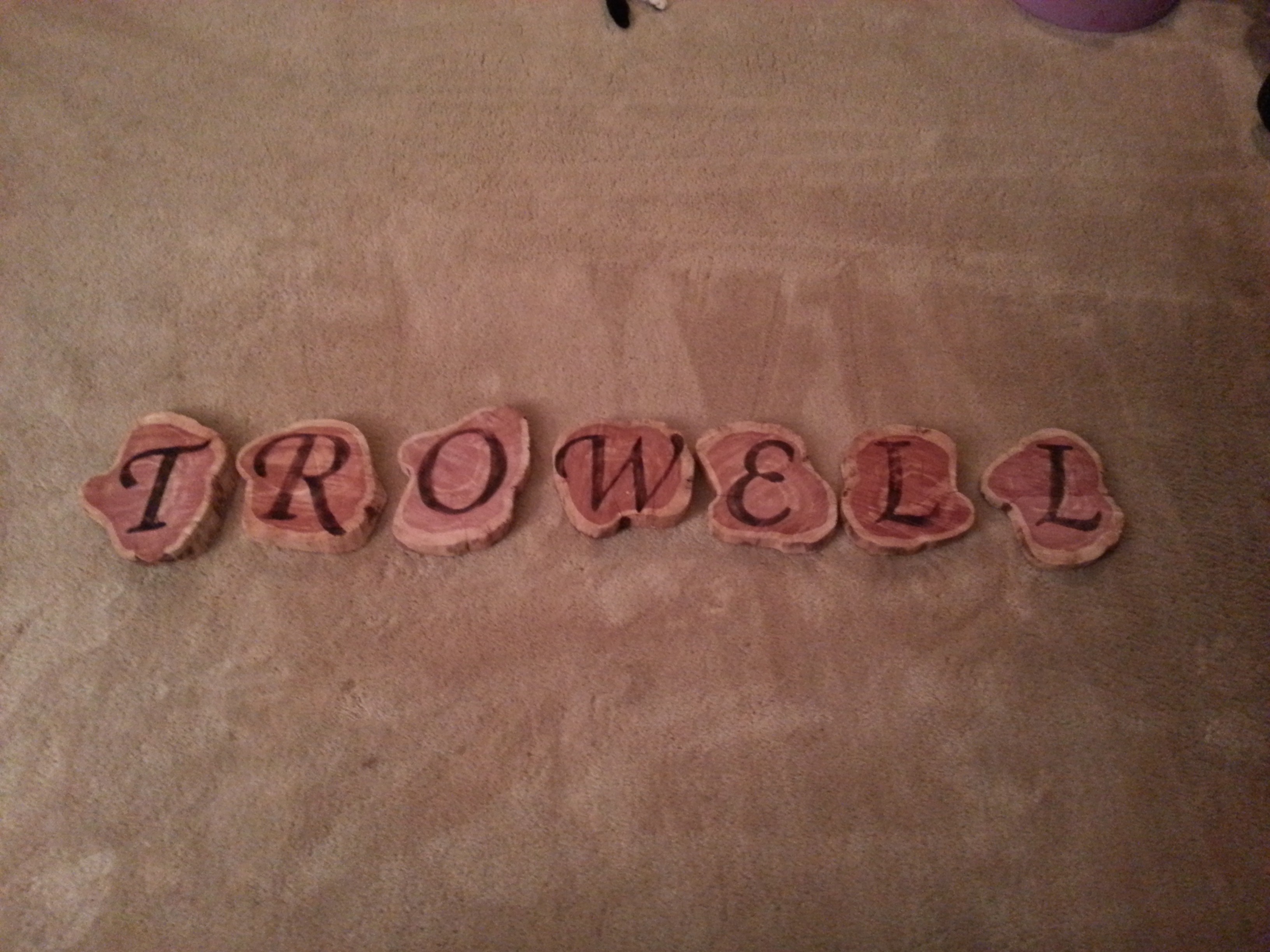
After burning the letters, remove the tape from the lightest letter to make sure that the contrast is good enough. If you fear it is too light, you may not be able to put the tape back on, and have to create an entire new letter. I chose to leave my light letters as is and call it "artistic".
When removing the tape you will find that the glue will want to stick to the wood at the edges of the letters. Do NOT use solvents to remove it. Use the sticky side of the tape you remove to dab the glue on the wood and it will gradually come off. I also think it helped that my wood was very rough, and the tape did not have a very smooth surface to stick to. Consider that if you plan to use finished wood you may have to do more testing to determine how many layers of tape are required.
Hangers
Add picture frame hangers to the back of the letters to hang them on the wall. My first idea was to use a dremmel to create a hanger pocket, but there is no way I could get the letters straight that way.
For the Night Light
You need:
- 2x npn transistor (any common switching transistor should work. I used 2n2222)
- "straw hat" through-hole white LED (I used this one, because it has a wide light dispersion rather than focused) Do not use a flashlight type high power LED. If you want a focused spot, use the appropriate round top LED.
- Phototransistor (I used this one).
- 220k resistor (may need to be different, see testing)
- 280 ohm resistor (may need to be different, see testing)
- Battery holder for 4 AA or AAA batteries
- Wire and solder as required.
Circuit
I first thought about a joule thief circuit, but after research decided not to use it because even though it will run on low voltage, it trades efficiency. I can use more batteries in series to get the voltage I need, and use a much more efficient current source circuit.
The applicable circuit is a very simple current source built from 2 transistors and 2 resistors, and uses the phototransistor to turn it on and off. The beauty of this circuit is that it accepts a wide range of voltage input without affecting the current draw. The cutoff voltage is just above the forward voltage of the LED, so it must be driven with 3 or more batteries. I chose 4 for convenience, giving me 6V nominal.
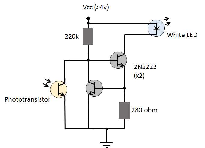
This circuit works by using the upper transistor to switch the white led on using current through the upper resistor (R1) when the Phototransistor is off. When the phototransistor is on, it shorts the base of the upper transistor to ground, shutting the white led off. The lower transistor and resistor (R2) set controls the current through the upper transistor.
The formula for the current control is I = Vbe/R. This 2N2222 spec shows a Vbe of 0.6V to 1.2V. Choosing the middle at 0.9V I made an initial calculation for a target 5 mA current giving R2 of 180 ohms.
Since the current draw when the circuit is off is related to the value of R1, this needs to be as large as possible to make the quiescent current as small as possible. Since the upper transistor must drive the led on, the resistor R1 must be able to supply enough gate current. The relationship is Ib=Ic/B where B is Beta. For the 2N2222, Beta is hFE at 1mA for this application, which is about 50. This means that the base current necessary to drive the led is about 5/50, or .1mA. So the initial reisitor size given a cutoff voltage of 4.5V is 4.5/.0001 = 45k ohms.
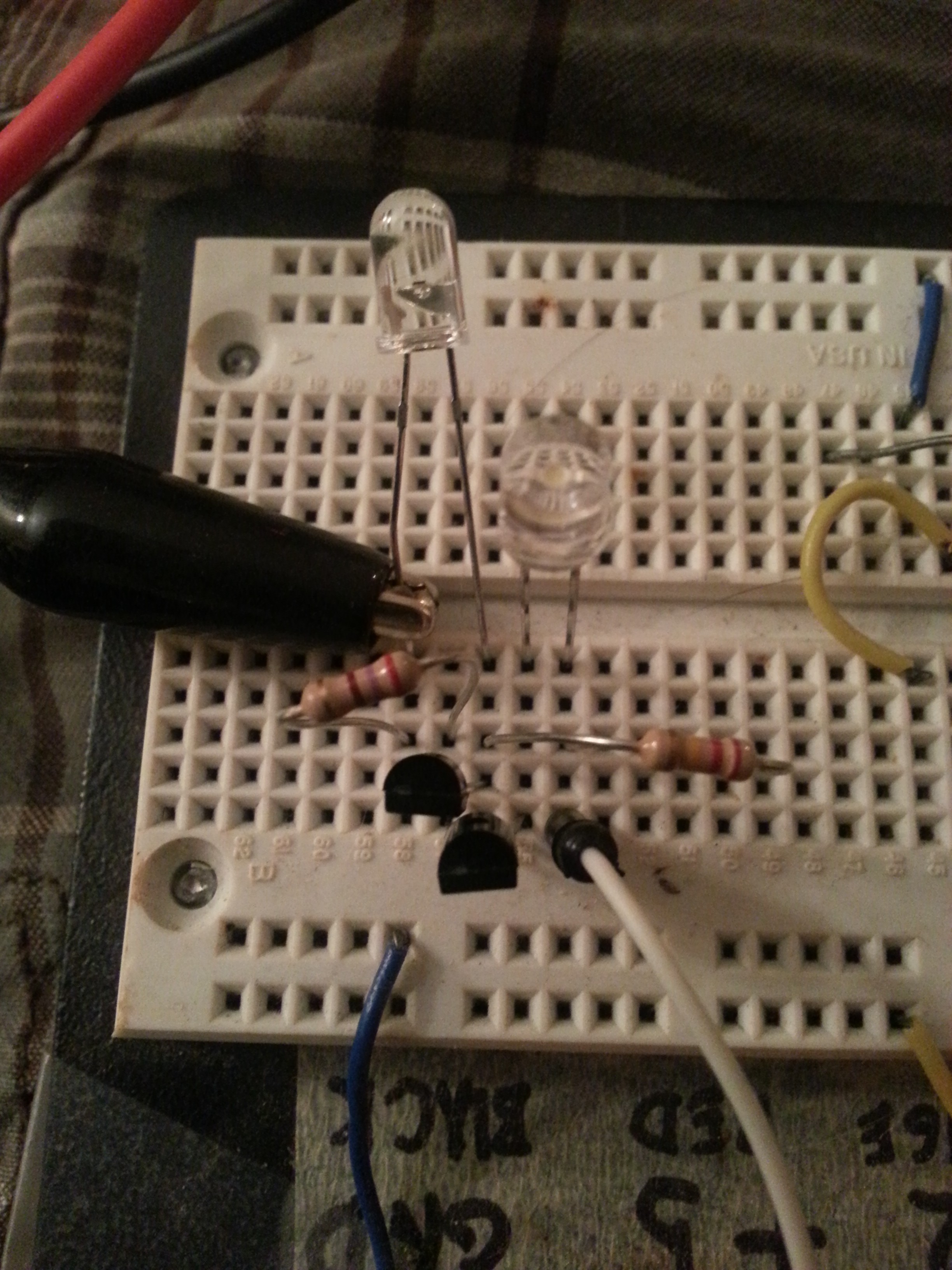
Prototype
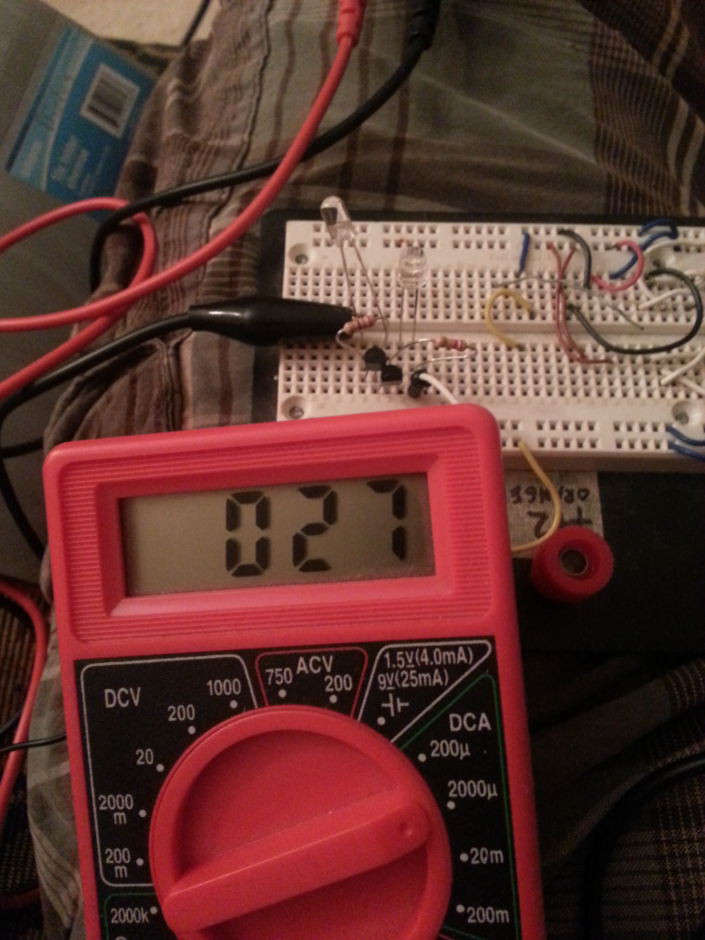
I built the circuit on breadboard with the calculated values and it worked! I connected a multimeter to measure the current draw and the system drew about 4.5 mA when the LED was on, and .1 mA when off. Fairly in line with the calculations! The LED was much brighter than I wanted, so I started to increase the value of R2 to bring the brightness down. After a few changes, the brightness was where I liked it and a value of 280 ohms was selected. You can adjust this to suit your needs. The current draw of the system with the LED on was now only 1.8 mA!
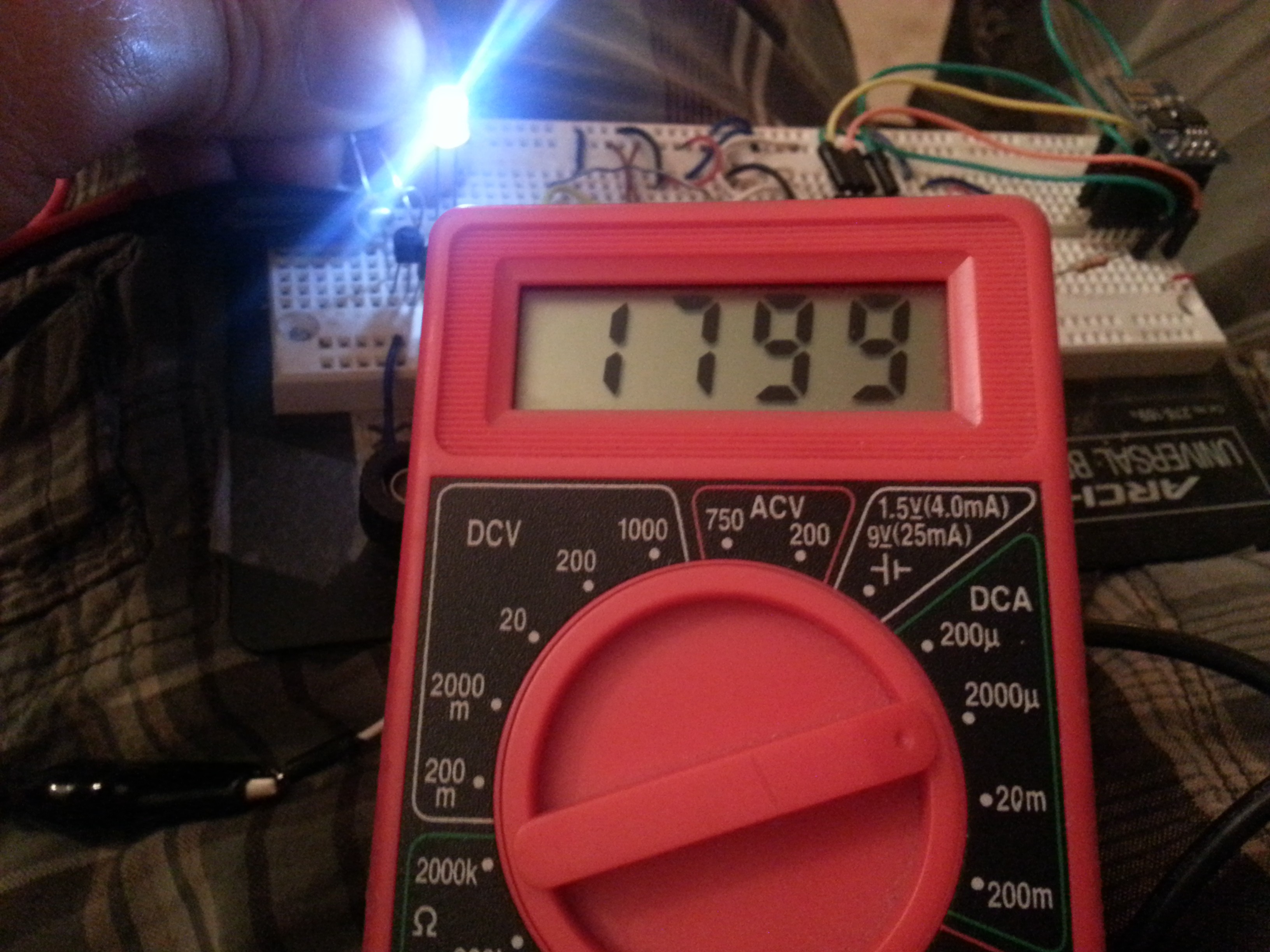
After I adjusted the brightness, I was not very happy with the .1 mA current draw when off. I decided to try increasing this value while the circuit was at the low voltage (for me 4.5V) to make sure the LED was being switched on. I inserted a 100k pot in line with the 45k resistor and started to slowly turn it up. After I maxed it out, I replaced the 45k with a 120k resistor and again started turning the pot up. When it maxed out a second time, without the LED visually changing, I checked the quiescent current with the LED off, and it was only 26 uA! Since the current draw of the LED when on was still 1.8 mA, I decided not to try to increase R1 any more. The transistor is in the linear range at this point, so the LED will dim as the ambient light grows.
One thing I noted is that the photodiode is very directional in detection, and responds to sun/incandescent light much better than fluorescent. At this point, the prototype worked amazing, and if driven with 4 AA batteries could potentially last a year!
 |  |  |
Assemble!
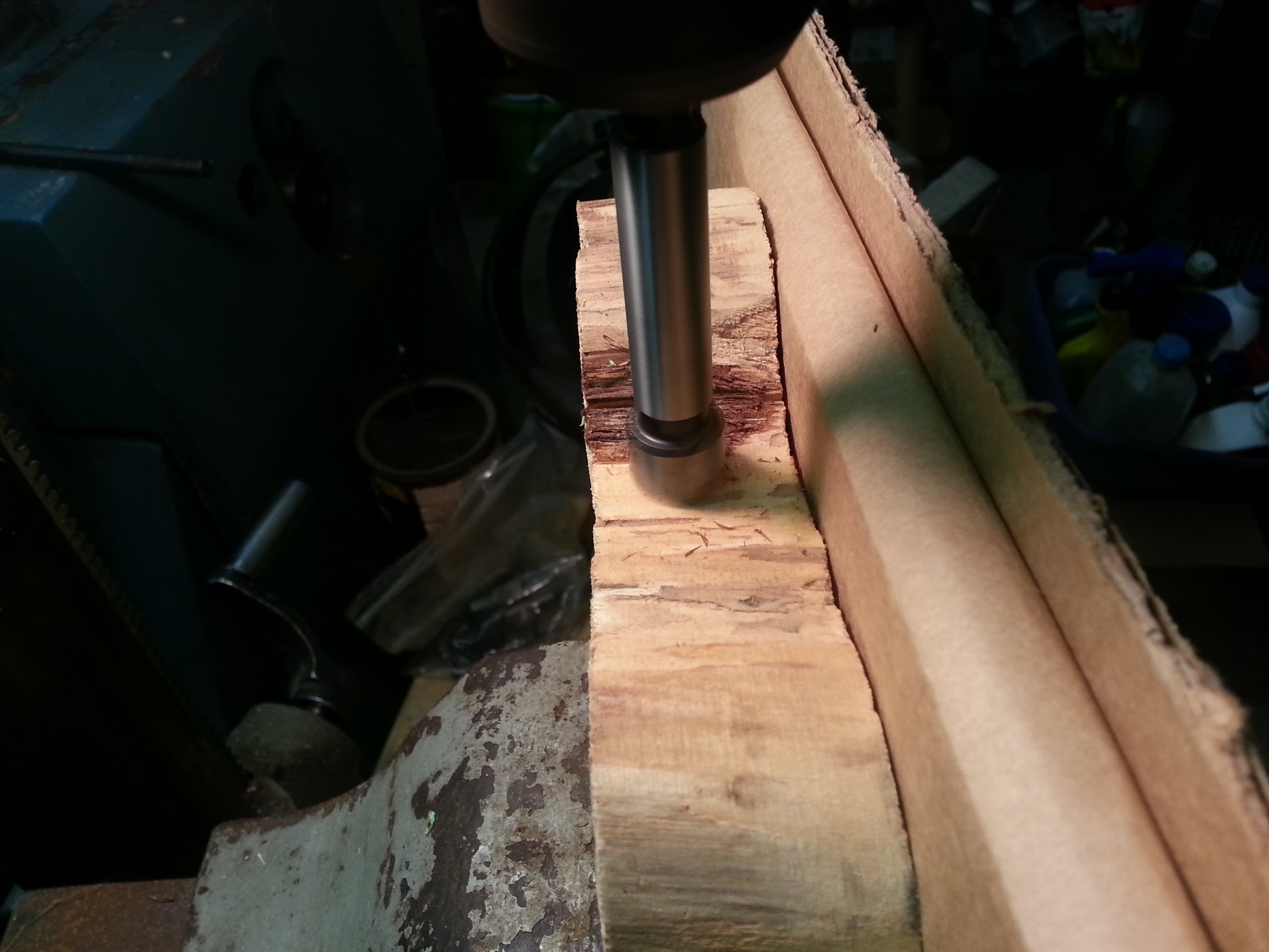
The biggest issue I had was how to integrate the battery holder into the shallow piece of wood. My solution was to drill holes into the bottom of the wood for each battery and use the wood itself as a battery holder. I wanted to get 2 batteries per hole, but my drill was only long enough to get one battery deep.
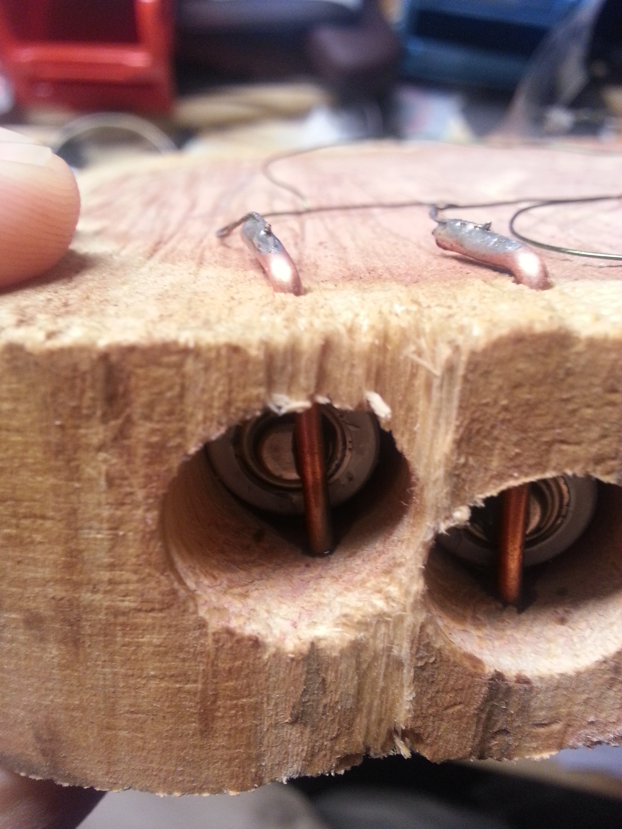
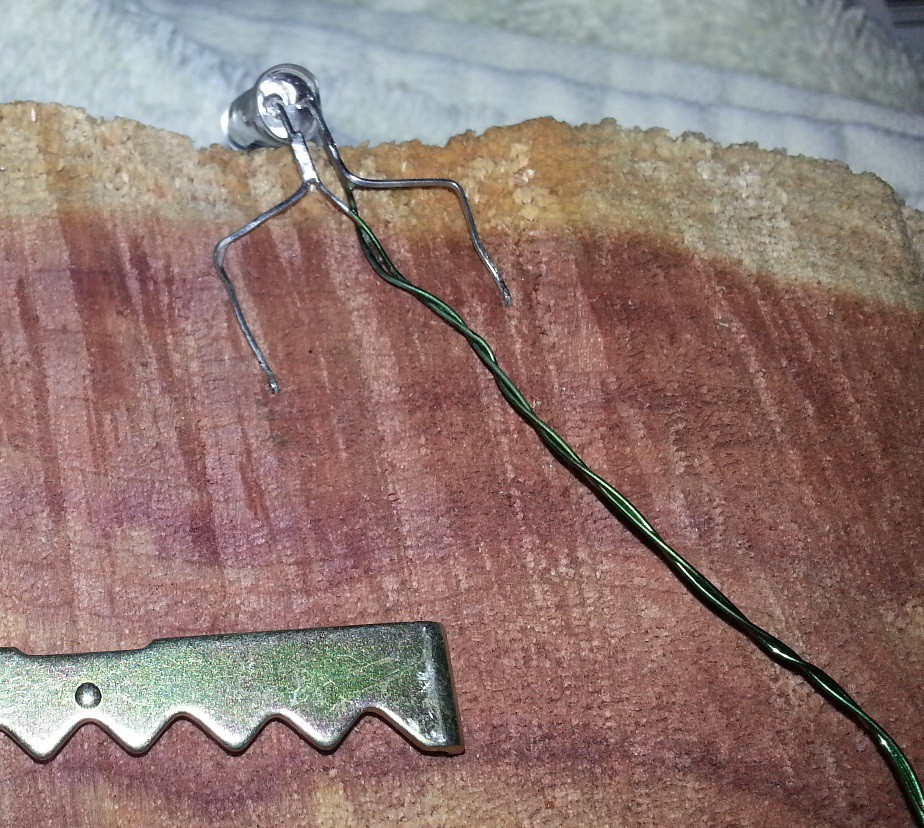
I removed springs from a broken battery holder and inserted them into each hole with enameled wire soldered on. Initially I was going to allow the enameled wire to run back up the battery hole, but I didn't think it would look good so I cross-drilled a hole for the wire near the bottom of each battery hole. To hold the batteries in, I used 12 ga solid copper wire with the insulation removed, inserted through cross-drilled holes. These were placed to require a slight compression of the spring at the bottom of the hole so that positive connection would be maintained.
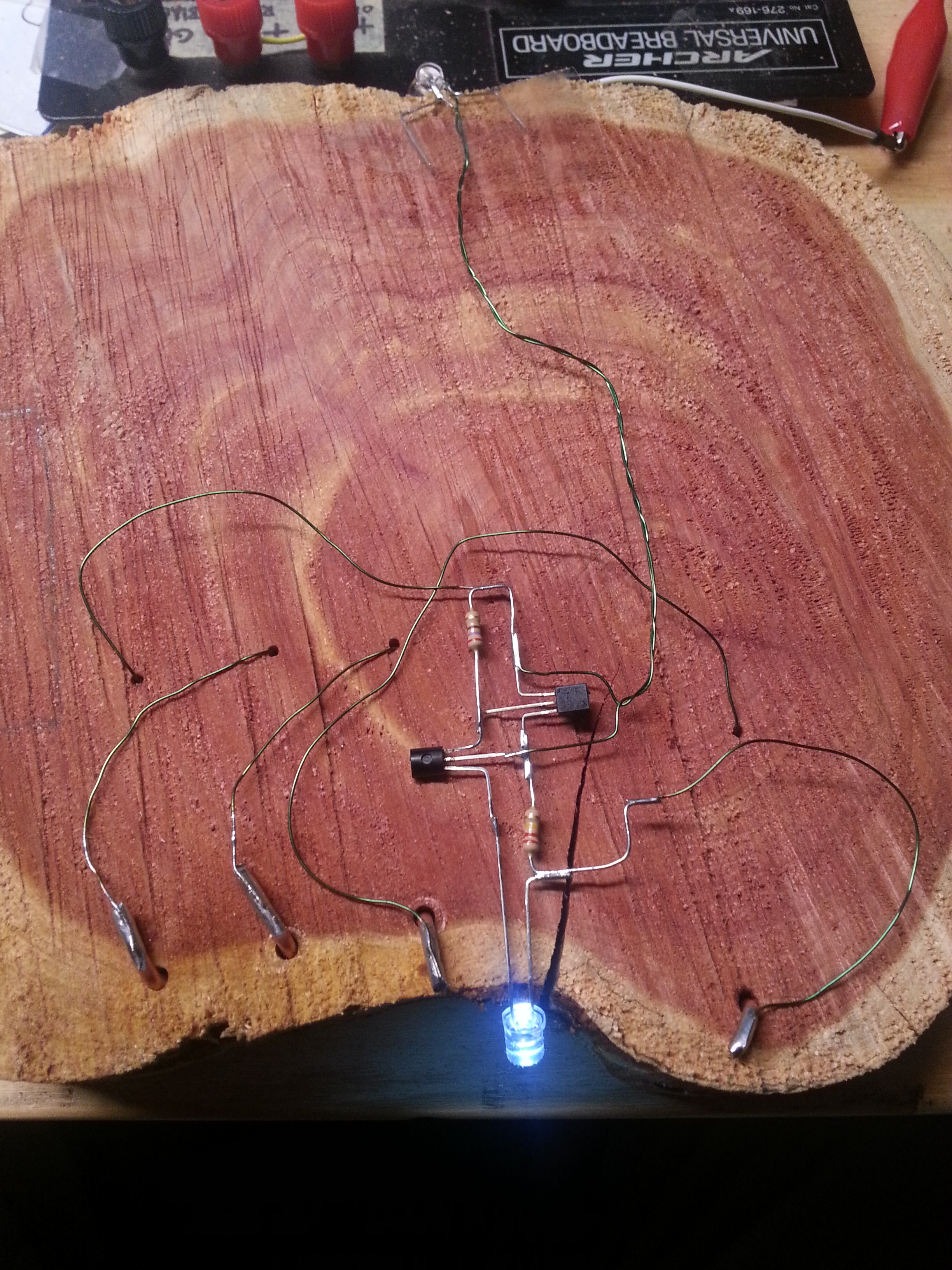
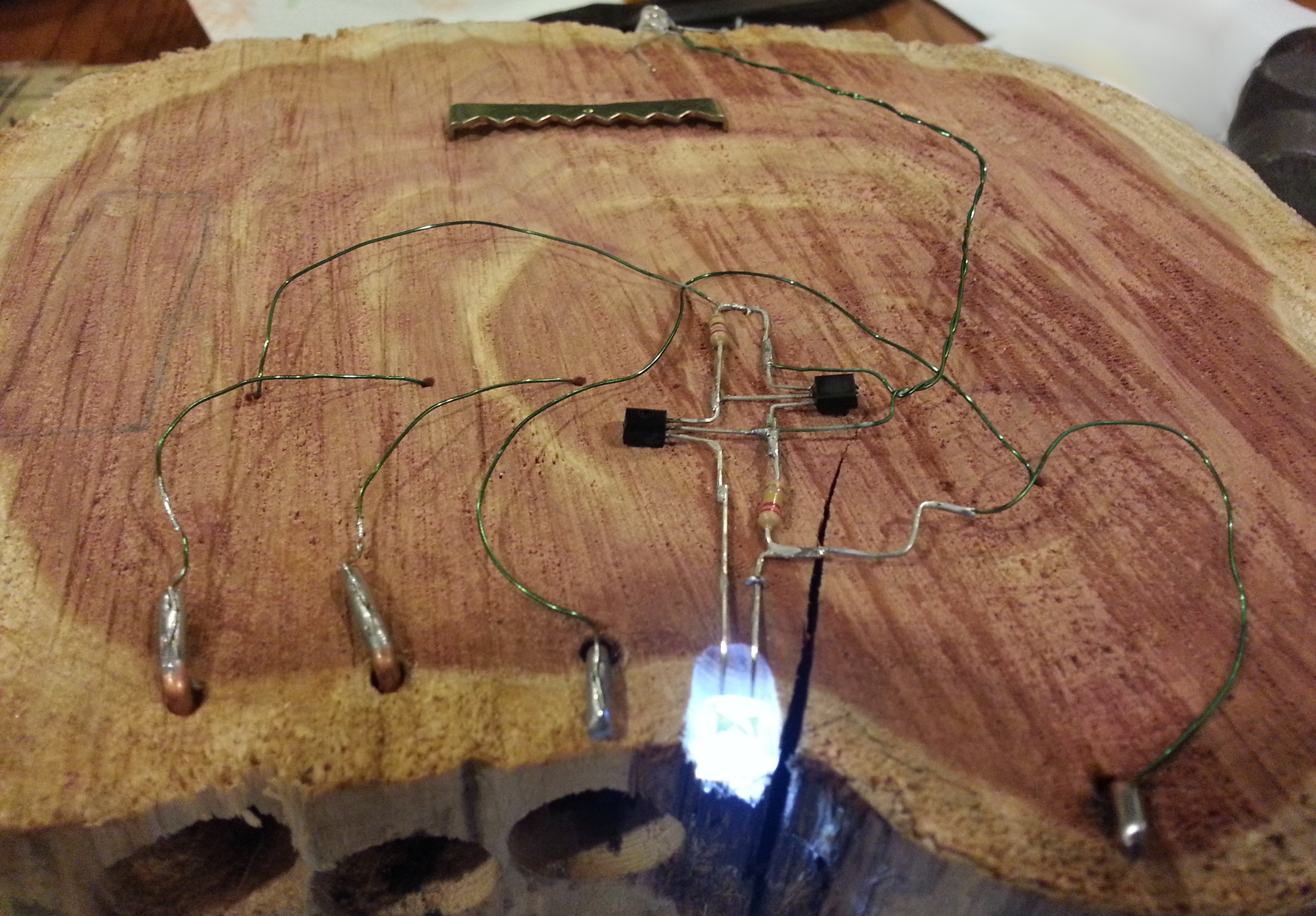
The circuit was soldered free-form and I tried to keep it artistic, with the components placed like you would see them in a schematic. I had thought about drawing the schematic next to the circuit, but couldn't think of a way to do it and have it maintain the look, so I left it off. With everything soldered together, it worked! You can see the small holes for the negative spring terminals above the larger copper wire positive terminals. The positive terminals can be removed from the holes to change the batteries. I made the mistake of making the first connection too short and I couldn't pull the large copper wire out to get the batteries in! After soldering, I cleaned all bare wire and sprayed the circuit with a clear epoxy to protect it. Hopefully it won't corrode!
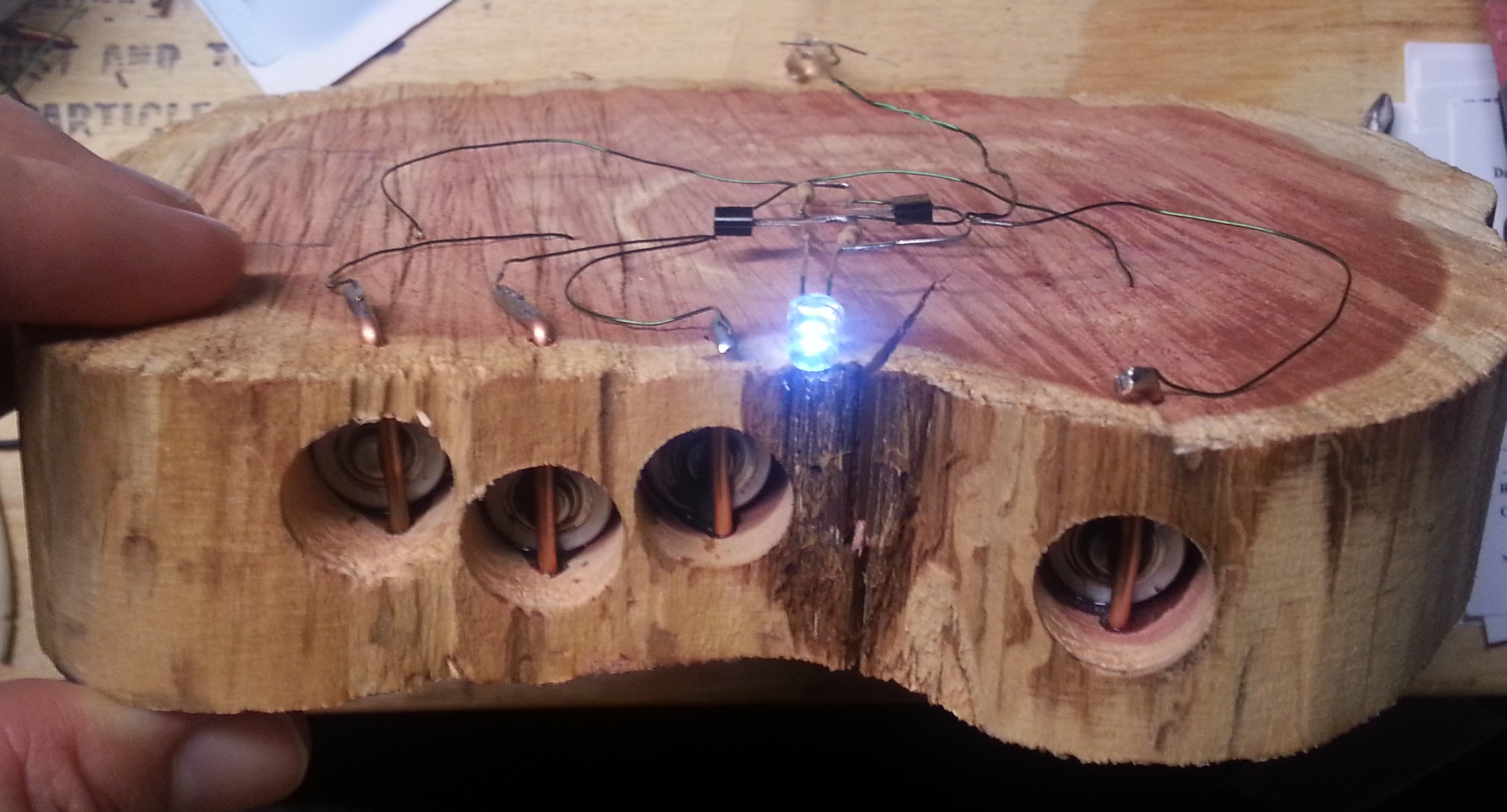
At this point I needed to fasten the circuit to the wood, so I made small staples out of some wire and hammered the staples in at the top and bottom (hard to see, but pictured in the following image between the resistor and led at the bottom, and all the way at the top of the circuit). I also bent the legs of the photodiode and hammered them into the wood to hold it in place. It should be noted that the photodiode does not activate very well with florescent light. In the case this is installed in a hall with a CFL, the photodiode will have to be moved to aim it directly at the CFL in order to shut the night light off.
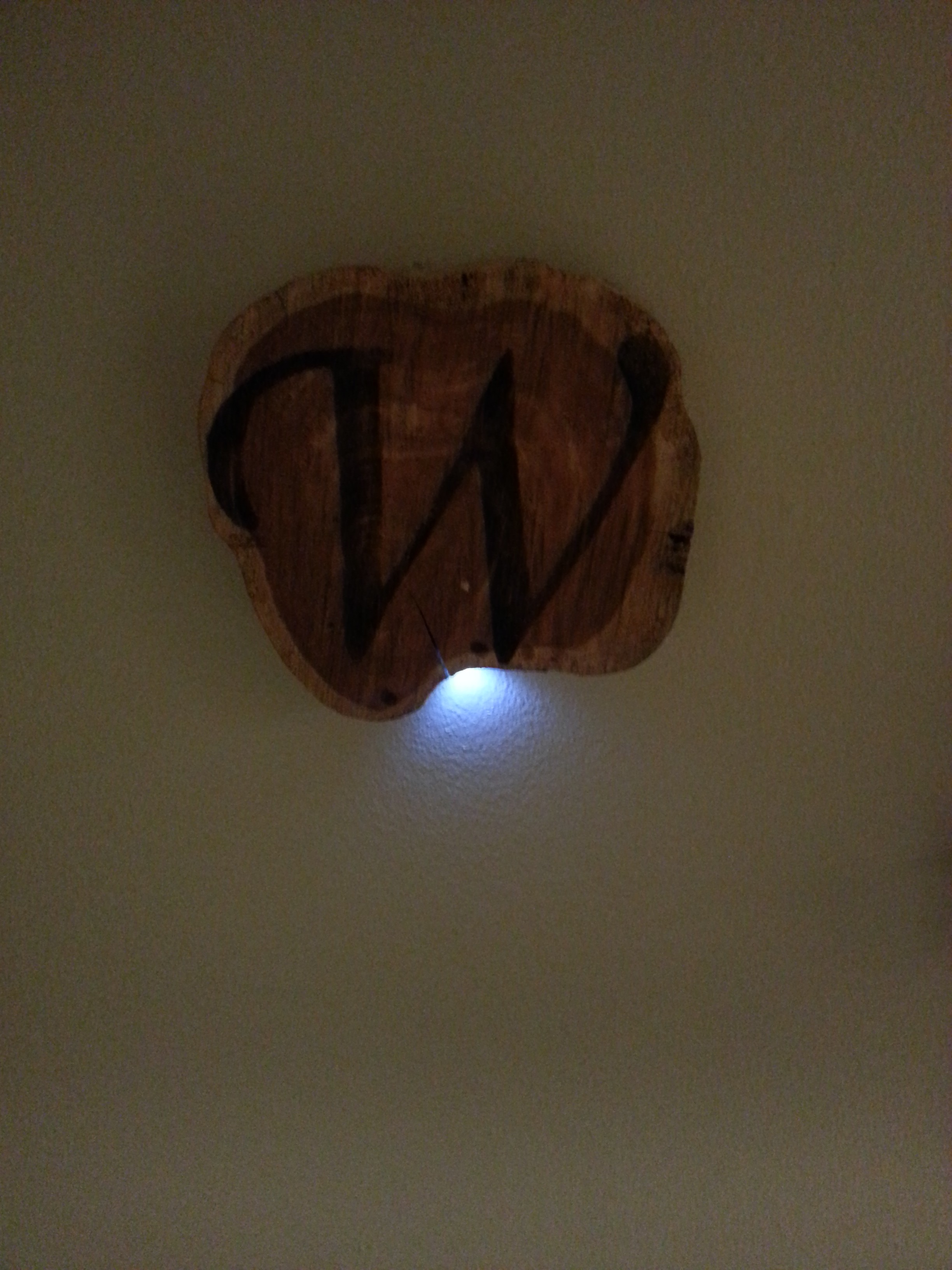
Completed Light!