 Ted Yapo
This project is really all about a resistor. Specifically, the 1.5M resistor, R3, in the schematic below.
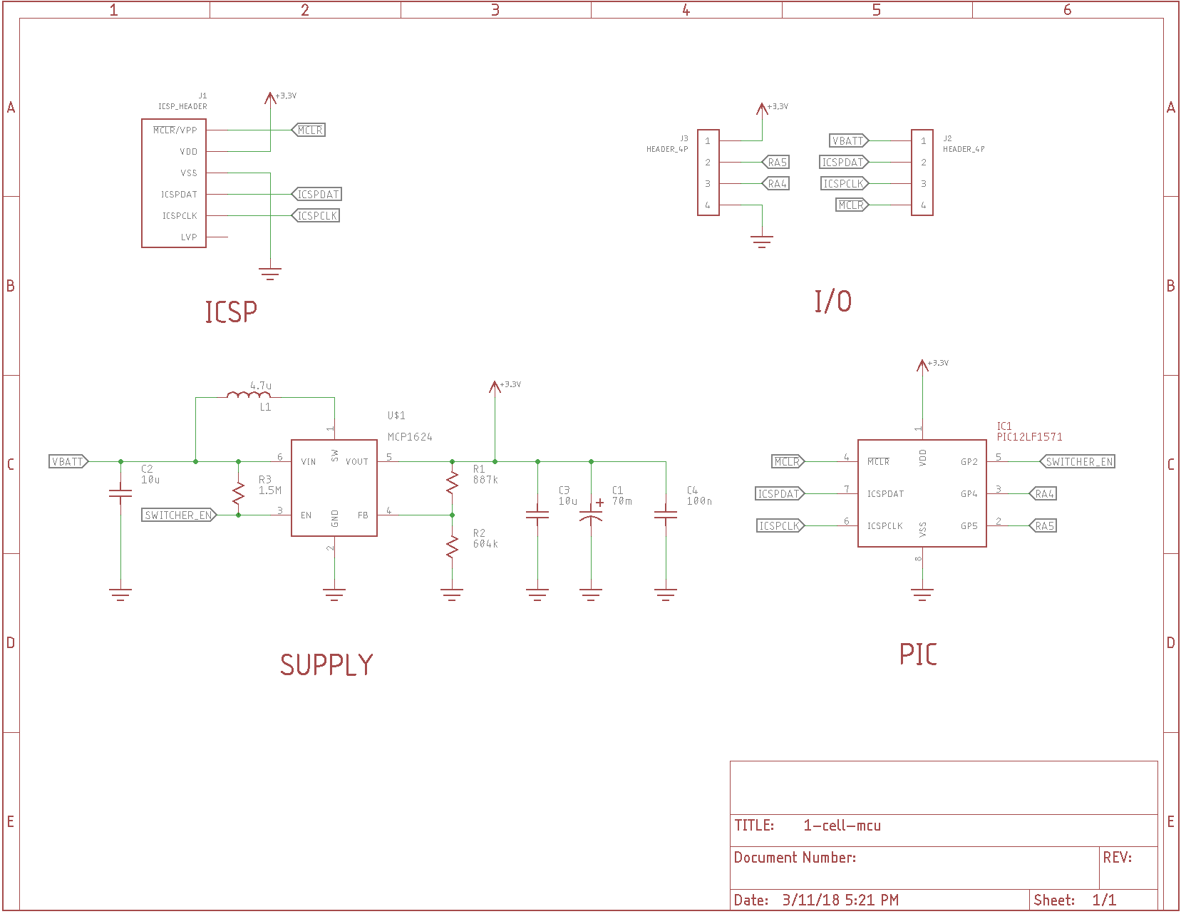
The MCP1624 is a DC-DC converter that will start at voltages as low as 0.65V (typ), so is ideal for running a PIC or other MCU from a single AA(A) cell or similar 1.5V nominal source (even button cells). But, it's not exactly nano-power. The graphs in the datasheet show a 100uA quiescent input current drain for a 1.1V source and 3.3V output, and it gets worse as the battery voltage falls. The goal of this project is to bring this current down.
The idea is that the PIC can shut down the converter during sleep or periodically when running to minimize the current consumption. I'll admit, having the PIC shut off its own power supply sounds like a recipe for disaster.
That's where R3 comes in.
When power is first applied, the PIC GPIOs are tri-stated, so R3 turns on the MCP1624 by pulling the enable input high. The MCP1624 comes on and charges C1, a 70mF supercapacitor, to 3.0V (selected with R1 and R2). When the PIC needs to sleep for a while, it can disable the MCP1624 by setting RA2 to an output and pulling it low. At this point, the PIC is running from the energy stored in the supercapacitor. This particular PIC has a low-power brownout reset (LPBOR), which will monitor the supply voltage and reset the PIC when the supply drops to a predetermined level. Should the PIC not wake up in time to re-enable the supply, the LPBOR will reset the PIC, which returns the GPIO pins to tri-state, starting the DC-DC converter again.
I expect that the normal mode of operation will be to set the sleep time so that this never happens, and the capacitor gets fully recharged periodically without the PIC resetting. But, the safety net is there just in case.
I'm grossly violating the 100uF maximum output capacitance spec for the MCP1624 with C1. I am hoping to get away with it due to the large ESR (100+ Ohms) of the selected supercapacitor. This 100-ohm ESR doesn't matter when the PIC is in sleep, consuming a few uA maximum, but hopefully is enough to keep the MC1624 stable. Now that I think of it, I should have added a site for an additional series resistor for C1 in case it's needed.
The leakage current for the supercapacitor also isn't specified. This could easily dominate the current drain. Plan B is to find some other large-ish, low-leakage capacitor(s).
I don't know yet exactly how low the sleep current will be, but I'm shooting for less than 5 uA.
I have some test PCBs ordered from OSH Park, and now just have to wait :(
The initial design is in the githubs. I tested it: it works!


 dave.m.mcdonough
 jbb
jbb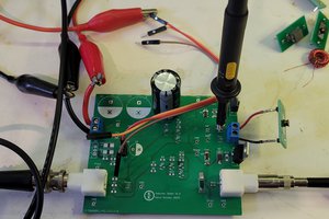
 Kevin Kessler
One thing to watch out for is the MCP1624 uses PFM at low power. The low switching frequency can mess up analog/audio circuit. MCP1263 would be better for those circuit as it has fixed frequency, but at the expense of lower efficiency. The high PWM frequency is easy to filter.
I learnt this lesson the hard way in my visual impair project a few years back.