Heather-Lynne Van Wilde
Settings would originally be configured using an SD card in the data logger, and would include SSID/passkey for WiFi, number of active sensors, moisture thresholds for each sensor and lighting schedule. WiFi would initially be used to contact a local NTP server to get the local time for data logging. Logging would be general status information (i.e. Lights turning on/off, watering cycle)
Potential future upgrades would include:
~ Sensor to monitor water tank level
~ Web interface to show current moisture status and recent events (making this more of an IoT system)
~ SMS/E-mail/Andorid push notifications of errors and alerts
~ Adding serial camera capabilities to take IR/UV photos (If we get this far, would probably have to upgrade to an Arduino Mega)
Details of parts list: http://pastebin.com/5V81YMuK
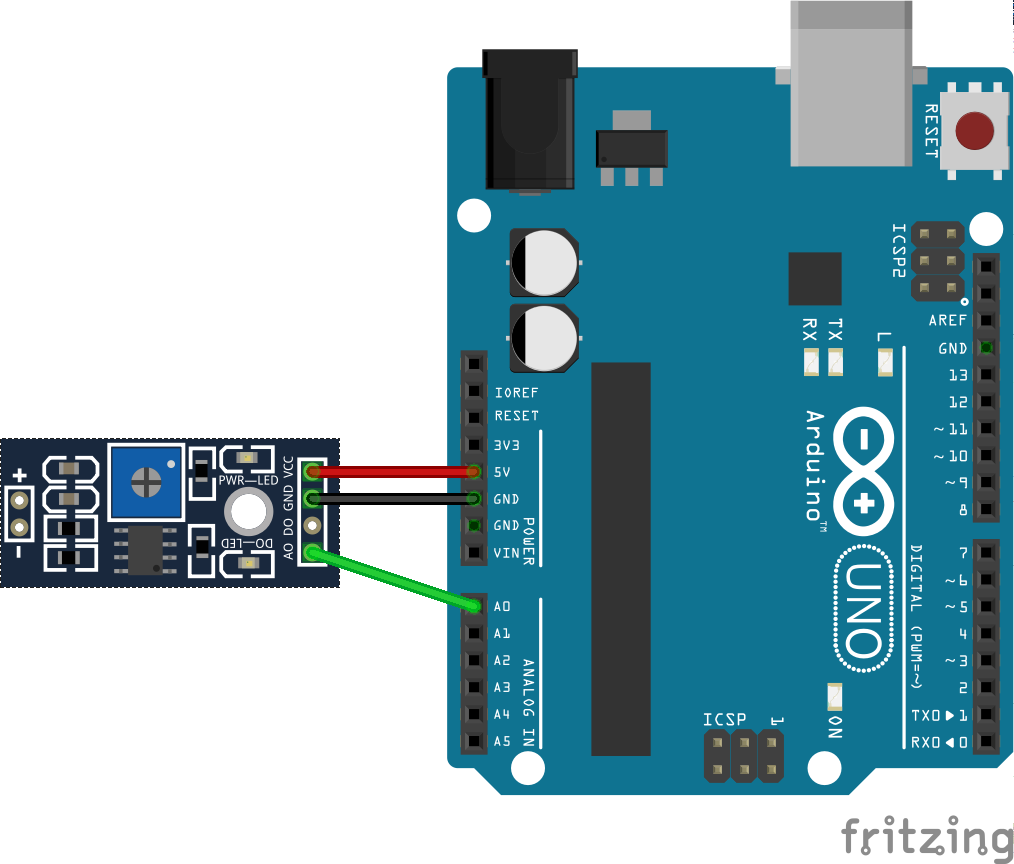
Original Inspiration: http://arduinosensors.com/index.php/soil-moisture-sensor-interface-with-arduino-uno/


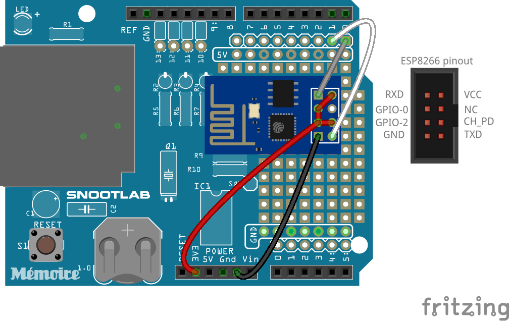

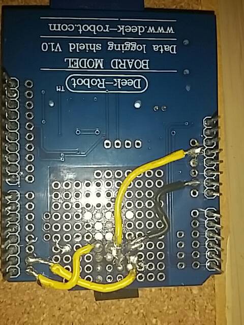

 Here's all you really need for this part. I'm doing it on the shield, just because I want to get used to having the other parts to worry about.
 jlbrian7
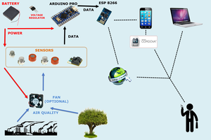
 Joshua Young
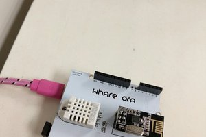
 Shiny
Shiny