 ottoragam
Quick Intro to Rotary Encoders
A mechanical rotary encoder uses a wiper (or wipers) that closes a circuit along a set of contacts distributed along a circumference. The wiper is attached to the shaft one is working with, and as this shaft turns, the wiper opens and closes a circuit, thus generating a pulse train that can be used to determine the angular position of the shaft (and its higher order derivatives with respect to time)by counting the number of pulses. A similar idea its used on the optical encoders, with the set of contacts replaced by a disk full of cutouts attached to the shaft, and a light source/photodetector that are placed on opposite sides of said disk to make the disk sequentially block and allow the light to shine onto the photodetector, again generating a pulse train containing useful Kinematic information.
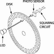 One light source/photodetector pair is useful if one does not need to determine the direction of rotation of the shaft. By adding a second set of cutouts (or a second light source/photodetector pair) 90 degrees out of phase with respect to the first one, one can detect the direction of rotation of the disk. Devices that employ this technique re called quadrature encoders, and they normally designate the photodetectors as A and B.
Enter the AS5040
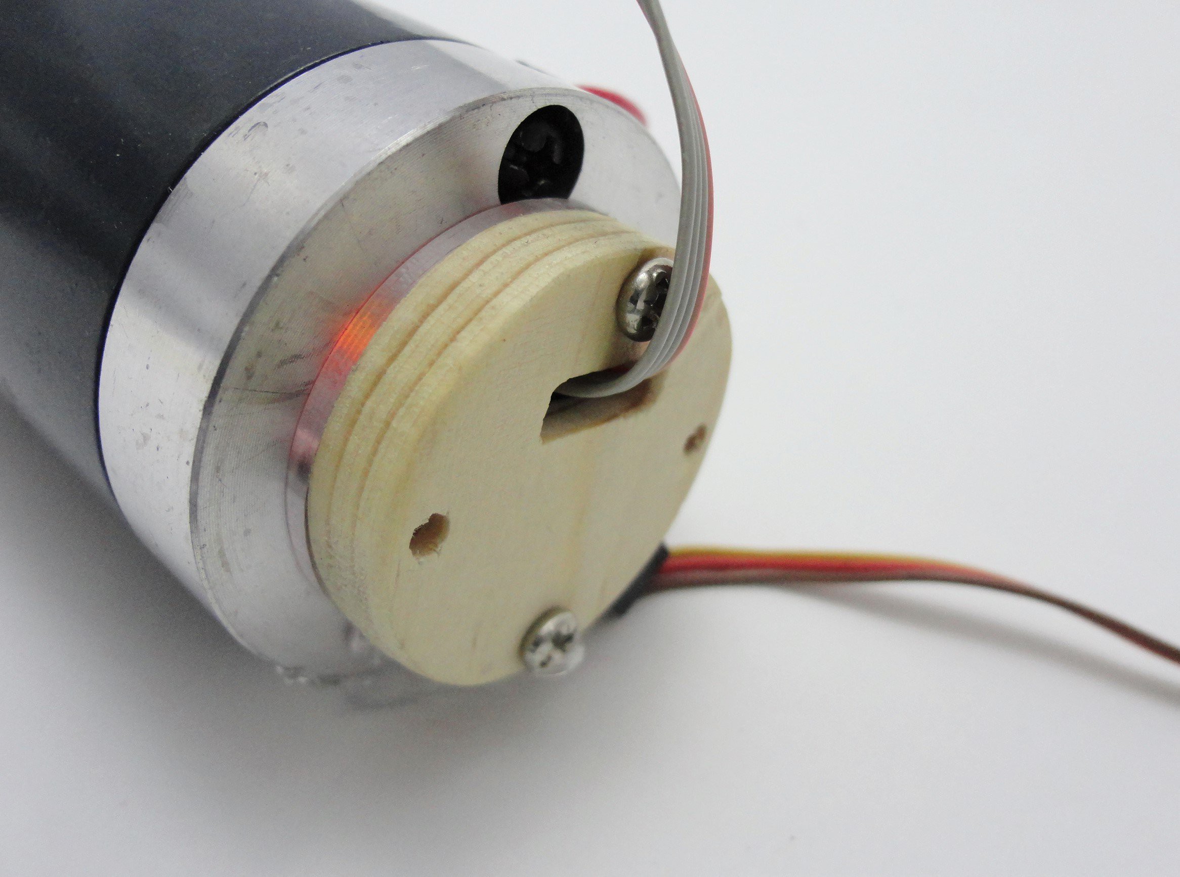
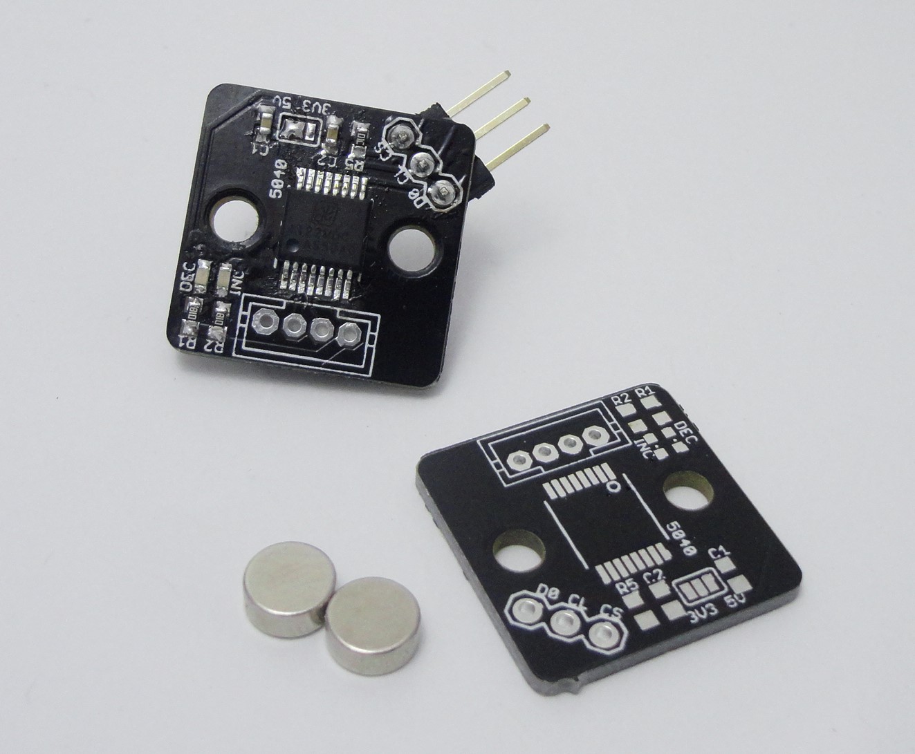
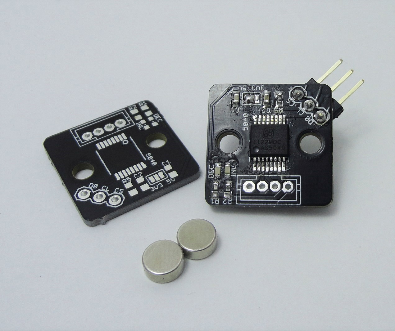
The AS5040 is sensor that detects changes in the angular position of the poles of a magnet, and outputs a two pulse trains, analog to the A and B outputs of optical encoders. I find this IC more versatile than an optical encoder. Some of its advantages are:
- End user settale resolution: 128, 256, 512 or 1024 state changes per revolution with 4x decoding.
- Only requires a two pole magnet to work.
- On chip decoding of the quadrature singnal.
- 30,000 rpm maximum speed!
- Operates at 3.3 V or 5 V.
- End user settable zero.
- Can be used as a brushless motor sensor.
The end user settable resolution its useful for avoiding bogging down the controller decoding the pulse train, specially at high speeds. Also, gluing a magnet onto a shaft and then alligning the PCB containing the sensor its easy, in contrast to fabricating a disk with 256 cutouts and mounting it to the corresponding shaft and light source/photodetector. Also, the final result is far more compact compared to the cheap otical encoders with similar resolution out there.

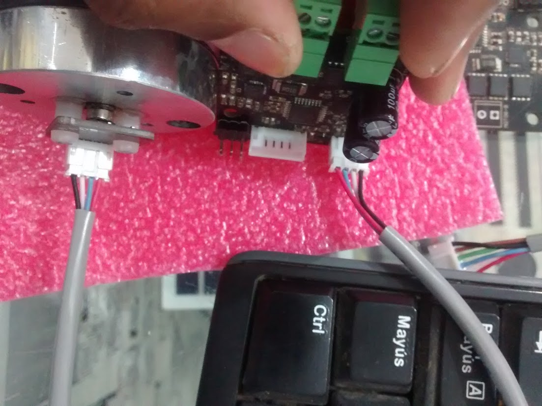
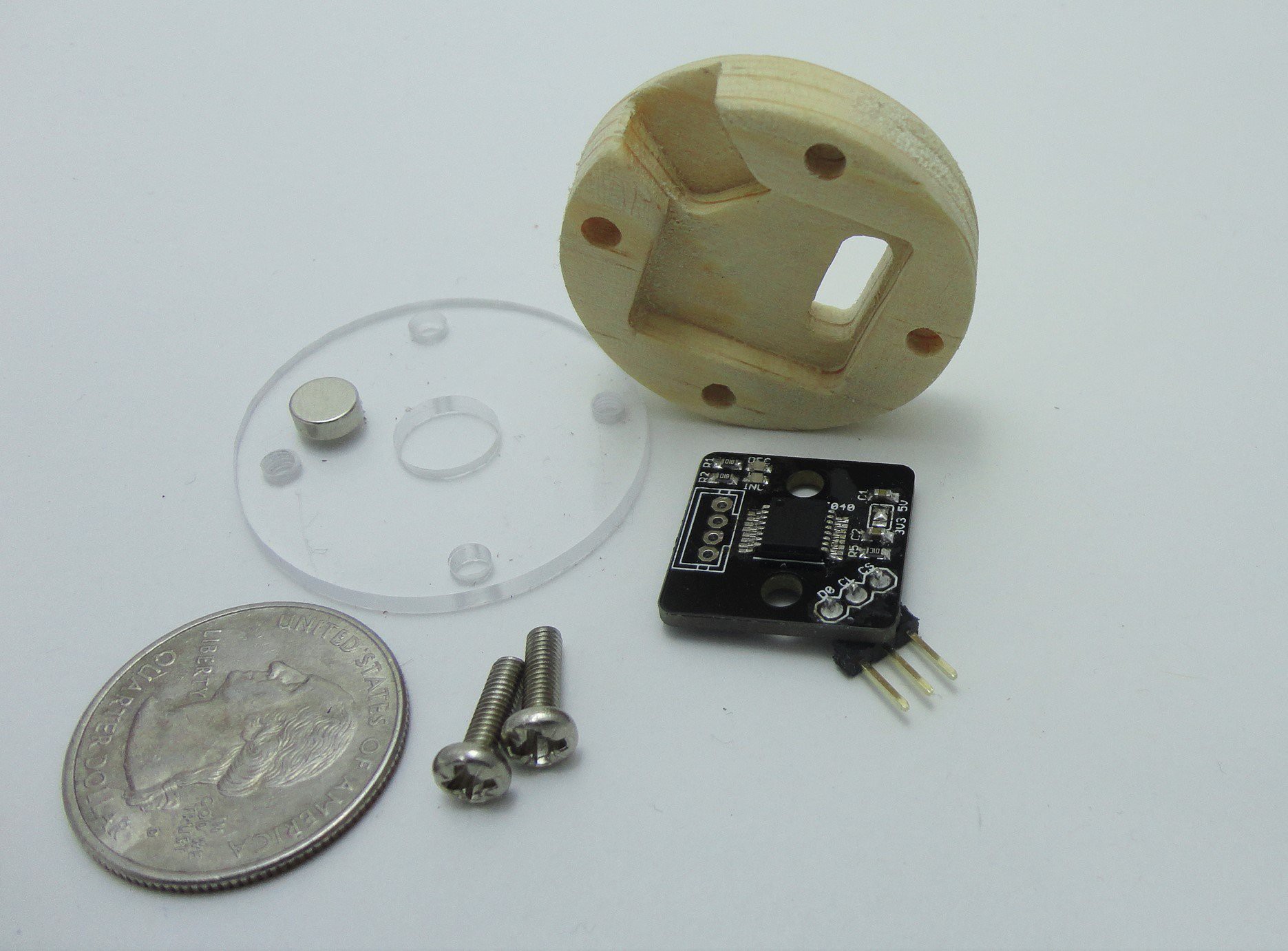 Here's the whole thing assembled. Notice that the IC must be facing the acrylic part.
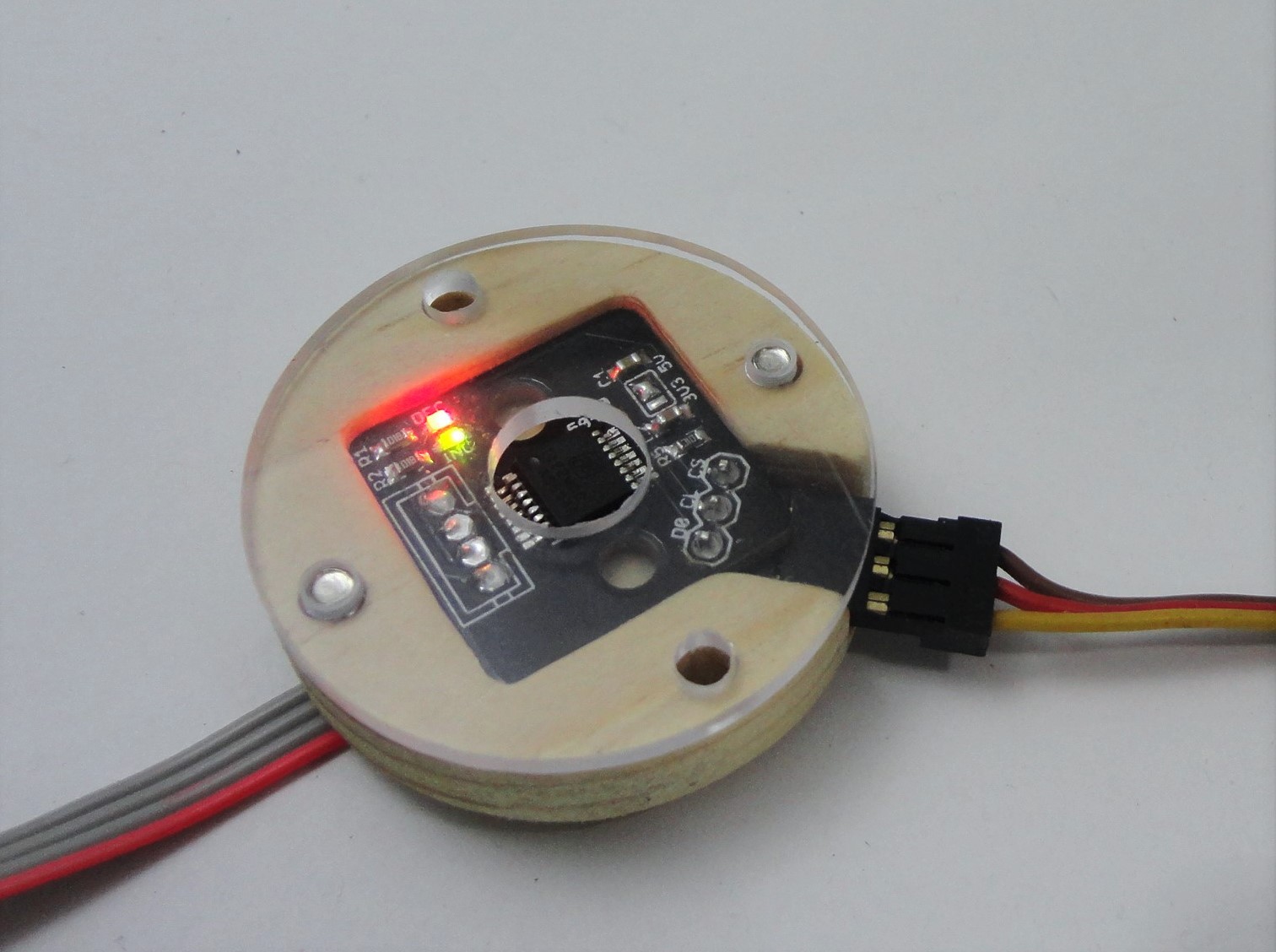


 Tamas Feher
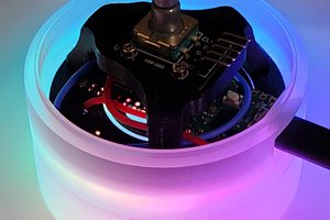
 Maximiliano Palay
 Antonio
 Thomas
i am looking for a way to connect 3 of these sensors to a single arduino . Is it possible ? i cant seem to find anywhere that how multiple seonsors can be used on a single mcu.