 ottoragam
The first PCB is ready, have a look at it!
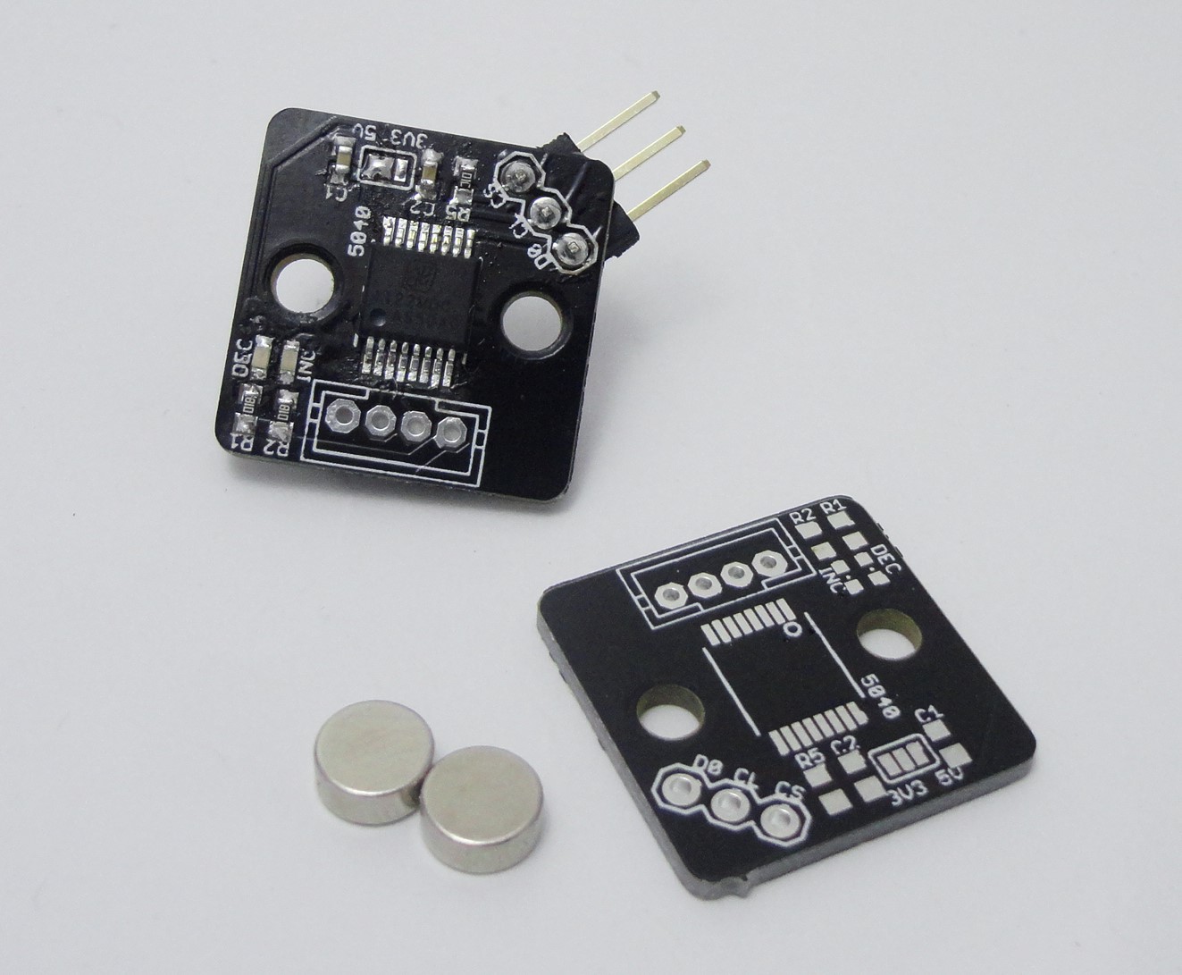
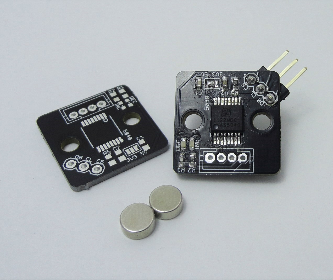
There are some design choices I would like to point out: rounded corners, separate connector for power/quadrature channels and programming, small size.
First, the rounded corners are important if one is going to machine an enclosure for this. Milling can only leave an interior corner with a radius as small as the endmill one's using.
With respect to the connectors, it is useful to have few signals in it. Instead of using the typical piece of ribbon cable for the signals, I planned to fabricate my own cable, using a JST-PH connector and shielded multiconductor cable for improved flexibility and noise inmunity. Good flexible multiconductor cable could get expensive, so it's better to use as few conductors as possible, leaving the signals that are not used all the time (i. e. spi programming header) on a secondary connector.
Many of the AS5040 projects out there that I found are more focused on being a breakout board for experimenting with this chip, and thus they're big, include things that are not needed for standalone operation, or are not really a finished product, and that's why I decided (also, The Square Inch Project) to create this board.
Discussions
Become a Hackaday.io Member
Create an account to leave a comment. Already have an account? Log In.