 Yann Guidon / YGDES
For practical reasons (it's impossible to list everything on the 'net), the "project" is mostly about gathering people from HaD who built their CPU (or at the very least digital electronic devices). Here are some external links for those who just can't get enough:
- http://www.ttlcpu.com/content/links
- http://members.iinet.net.au/~daveb/simplex/ringhome.html => moved to http://homebrewcpuring.org/
- http://www.bigmessowires.com/nibbler/
- http://www.alles.or.jp/~thisida/mycpu_tk80photo.html
- https://en.wikibooks.org/wiki/Microprocessor_Design/Wire_Wrap
- http://www.megaprocessor.com
- http://www.witch-e.org (https://hackaday.io/project/19955-witch-e )
- http://monster6502.com
Feel free to suggest or add links of the same kind :-)
PS: the project's logo comes from Wikipedia
PPS: let's not forget the two lists https://hackaday.io/list/2402-homebrew-computers and https://hackaday.io/list/25846-homebrew-cpu but note they are subject to curator delay (and taste).
Logs:
1. Dynamic RAM with single MOSFET per bit ?
2. Bizarre DTL Logic Levels - The Discrete Component PDP-8
3. The Electronics of IBM Standard Modular System Logic
4. ECL or CTL : what's the fastest topology for discrete gates ? [updated]
5. TTL inside
6. Direct Coupled Transistor Logic
7. Interactive Simulations of DEC R-Series Logic
8. Why is ECL faster ?
9. Bipolar XOR gate with only 2 transistors
10. Video Explaining DEC R-Series DTL
11. The rule of 50 (or so)
12. Bipolar transistors are ANDN gates !
13. The return of CTL
14. From XOR to MUX
15. From MUX to Latch
16. Project proposal : Ring oscillators zoo !
17. Analog Multiplexer Logic
18. Another RTL/DCTL latch
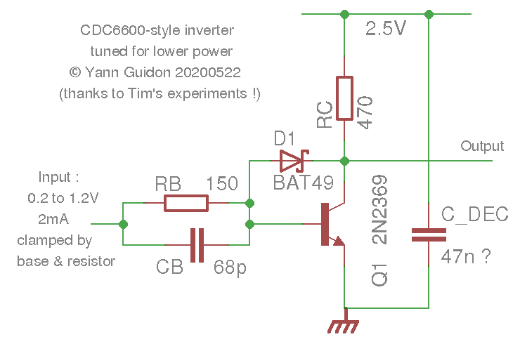
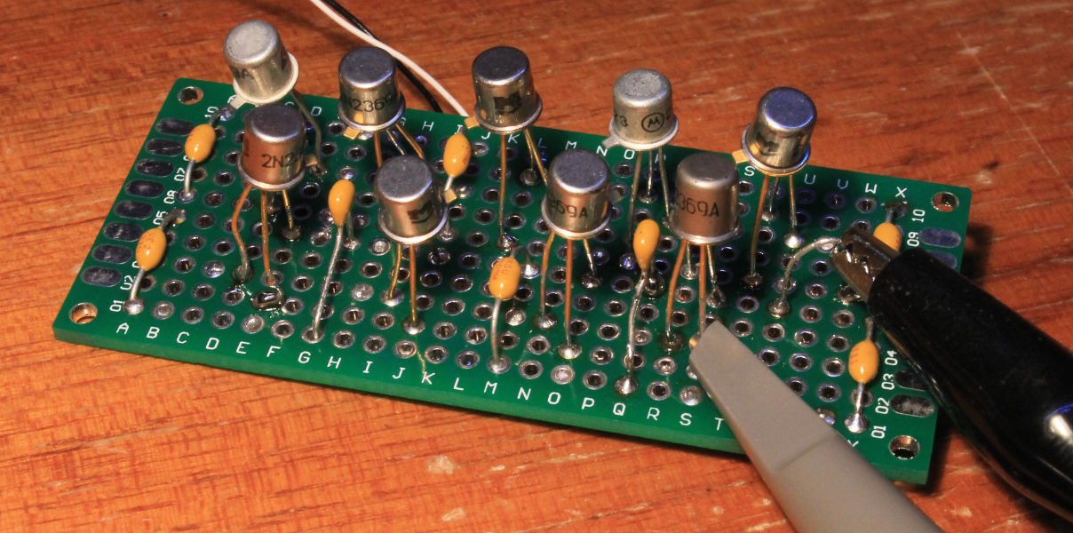
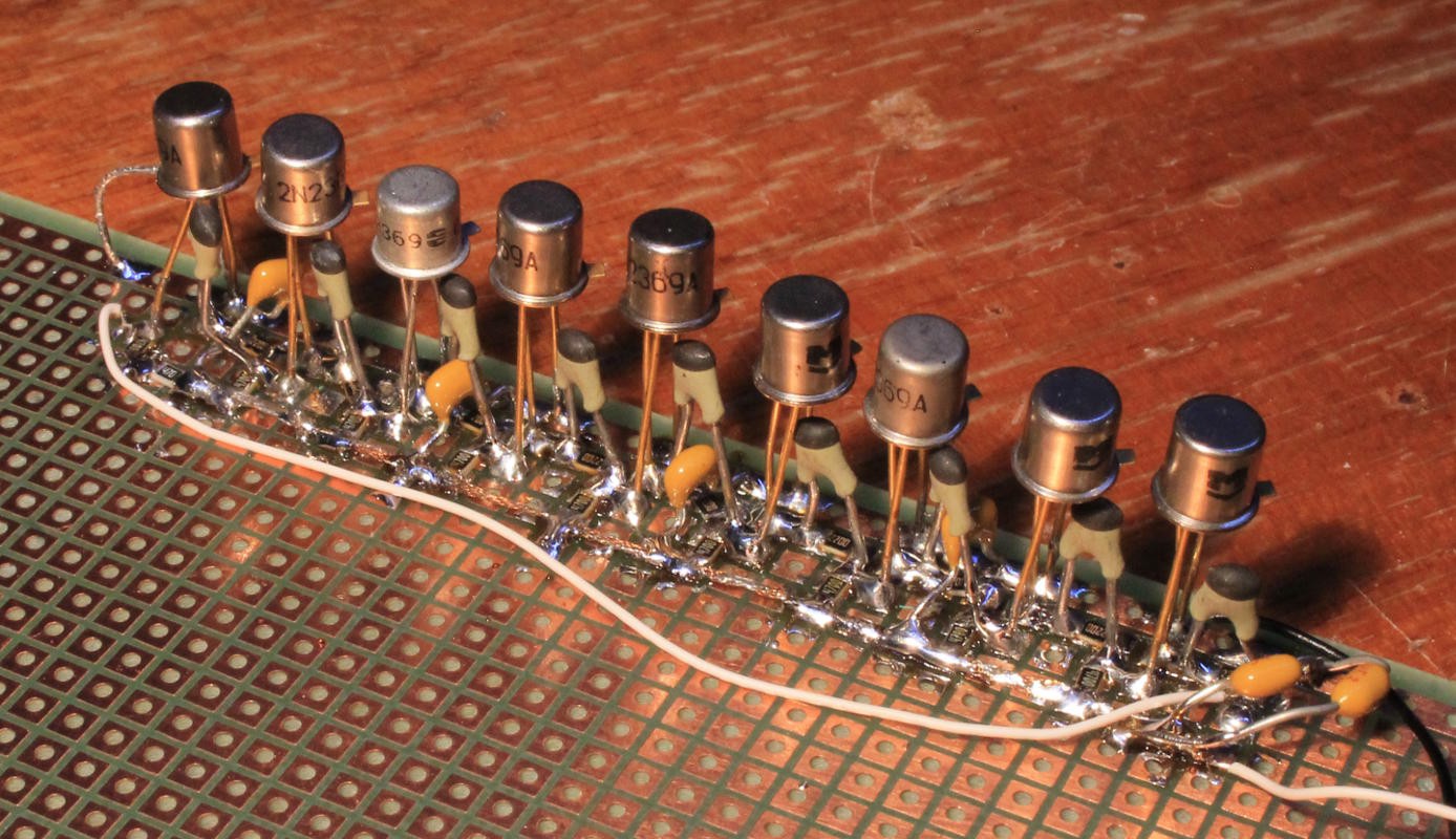
19. My own try at a RingO9 with 2N2369A
20. unexpected frequency doubler or rectifier
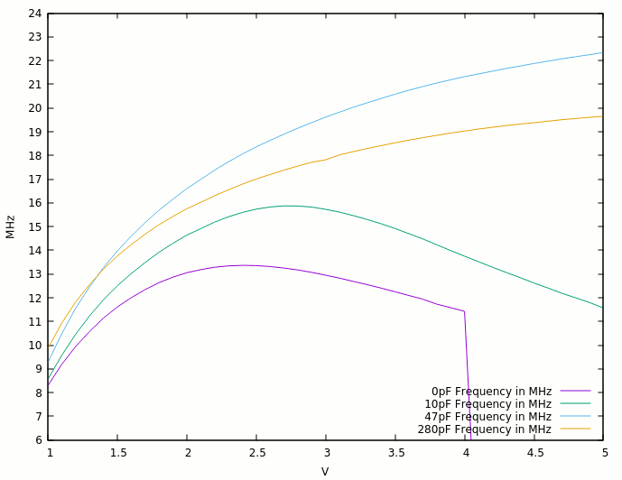
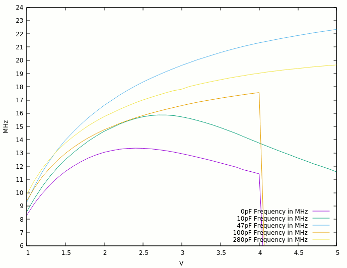
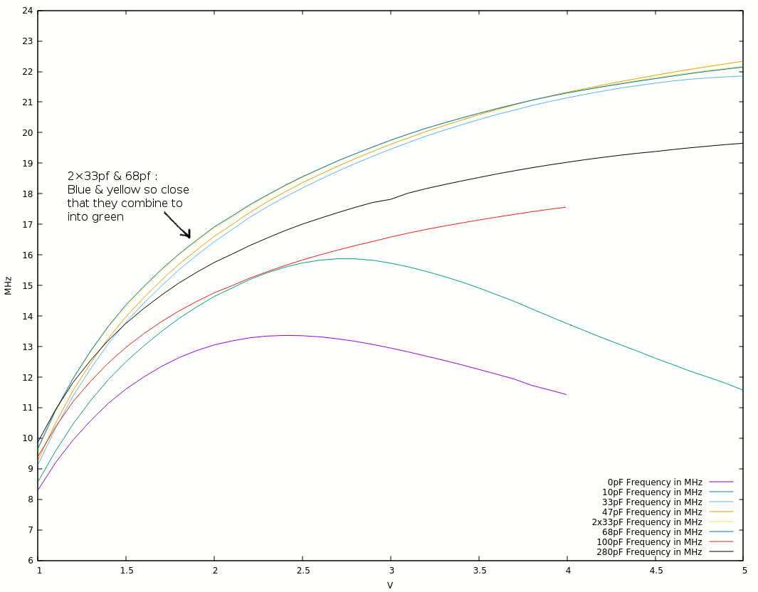
21. More 2369, with more caps !
22. RingO9 v2 : closer to CDC specs !
23. RingO9 v2 : with caps !
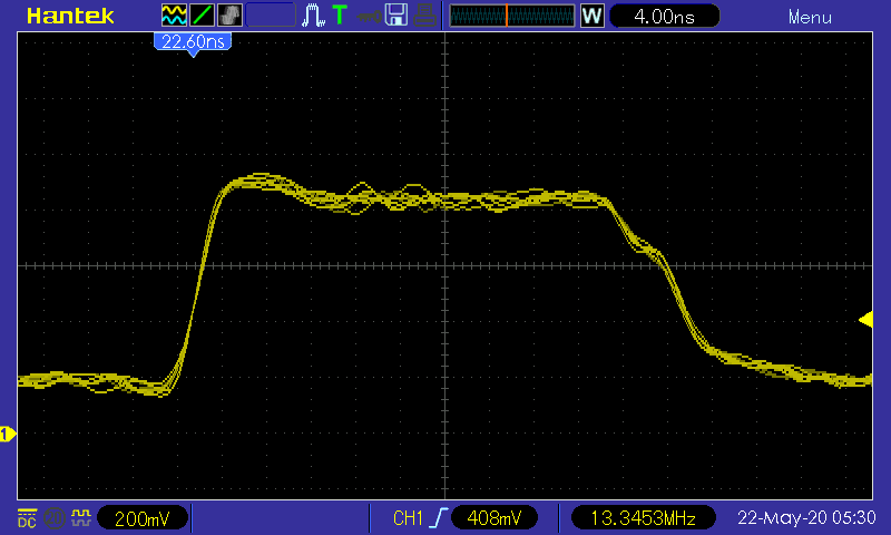
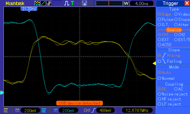
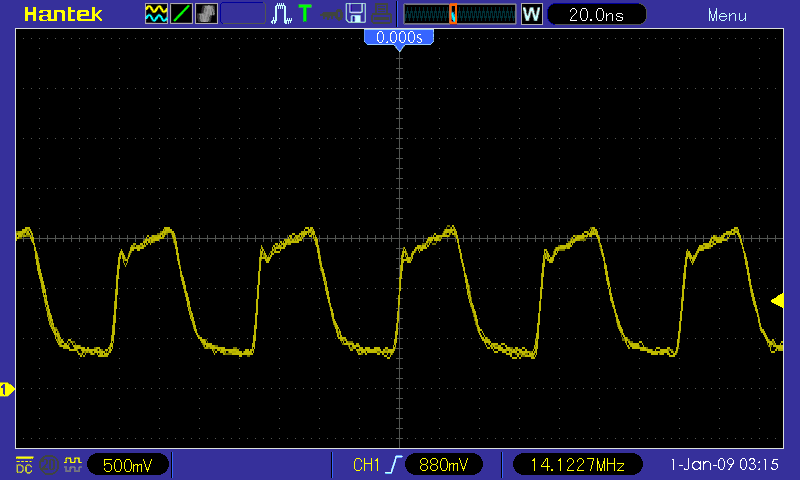
24. Beyond 2ns with 2N2369A
25. Dear Marcel
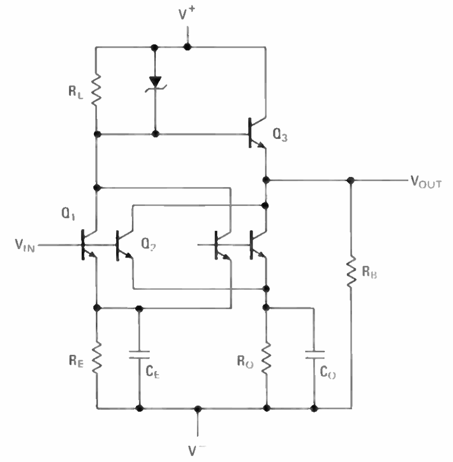
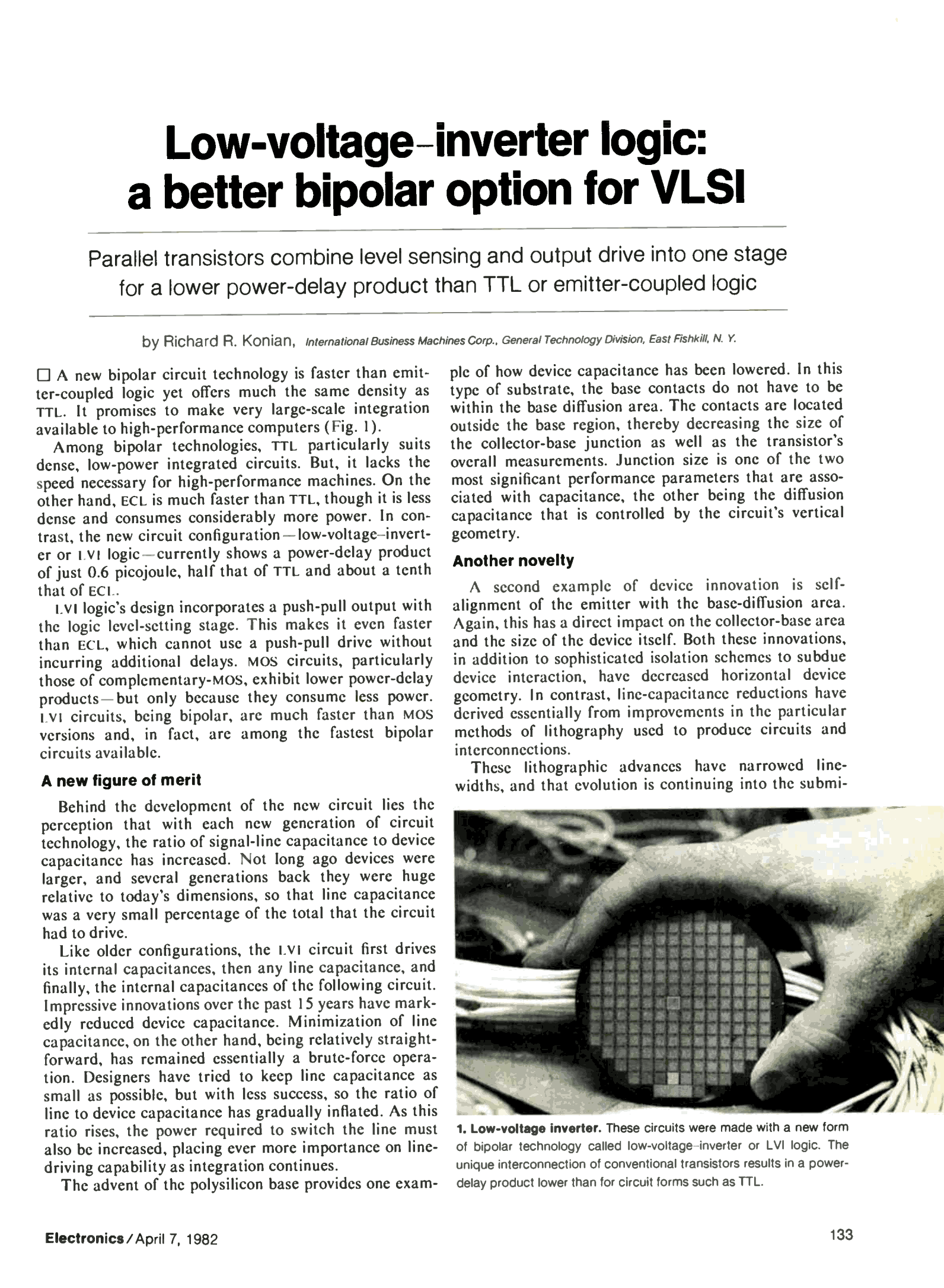
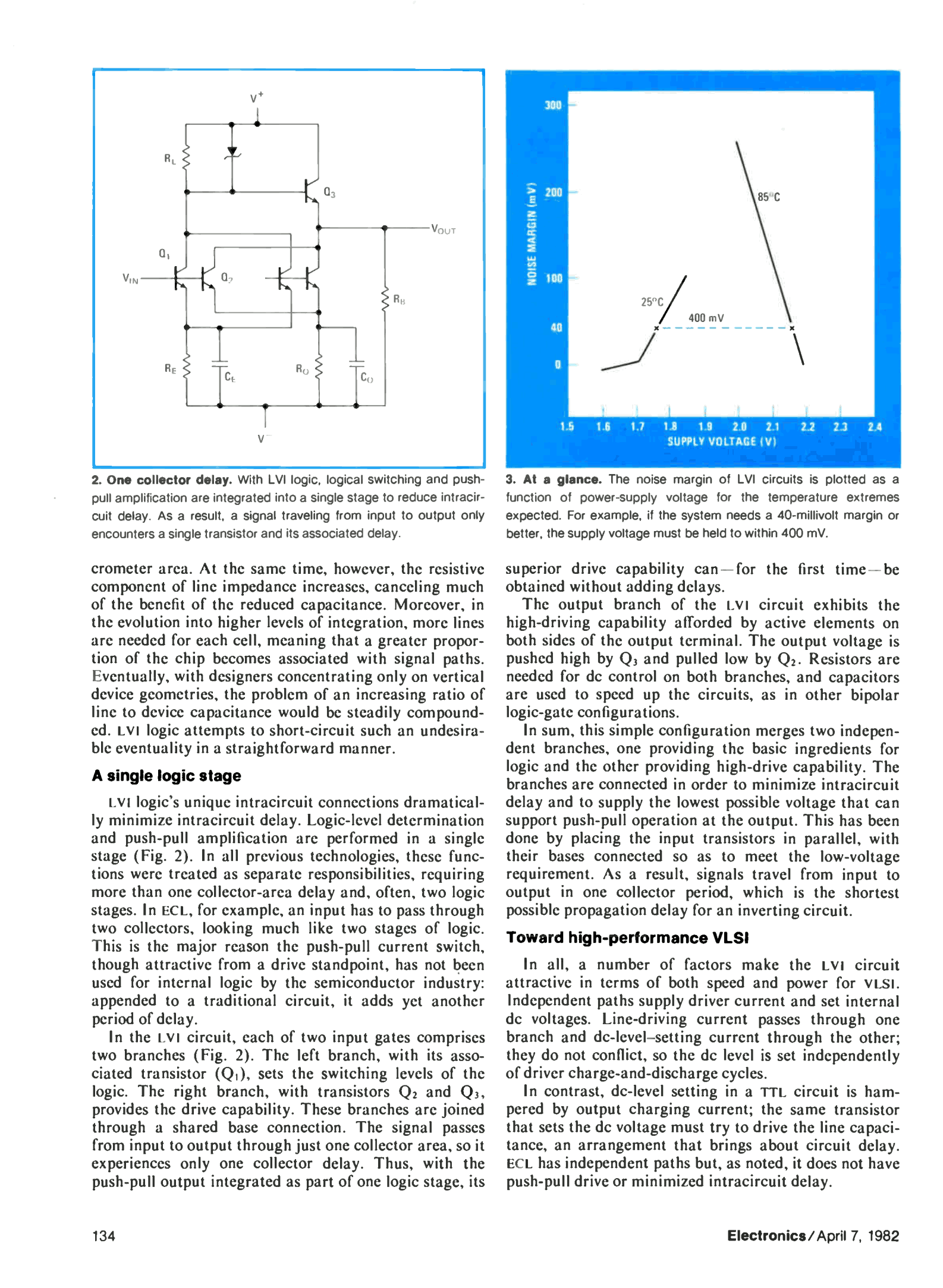
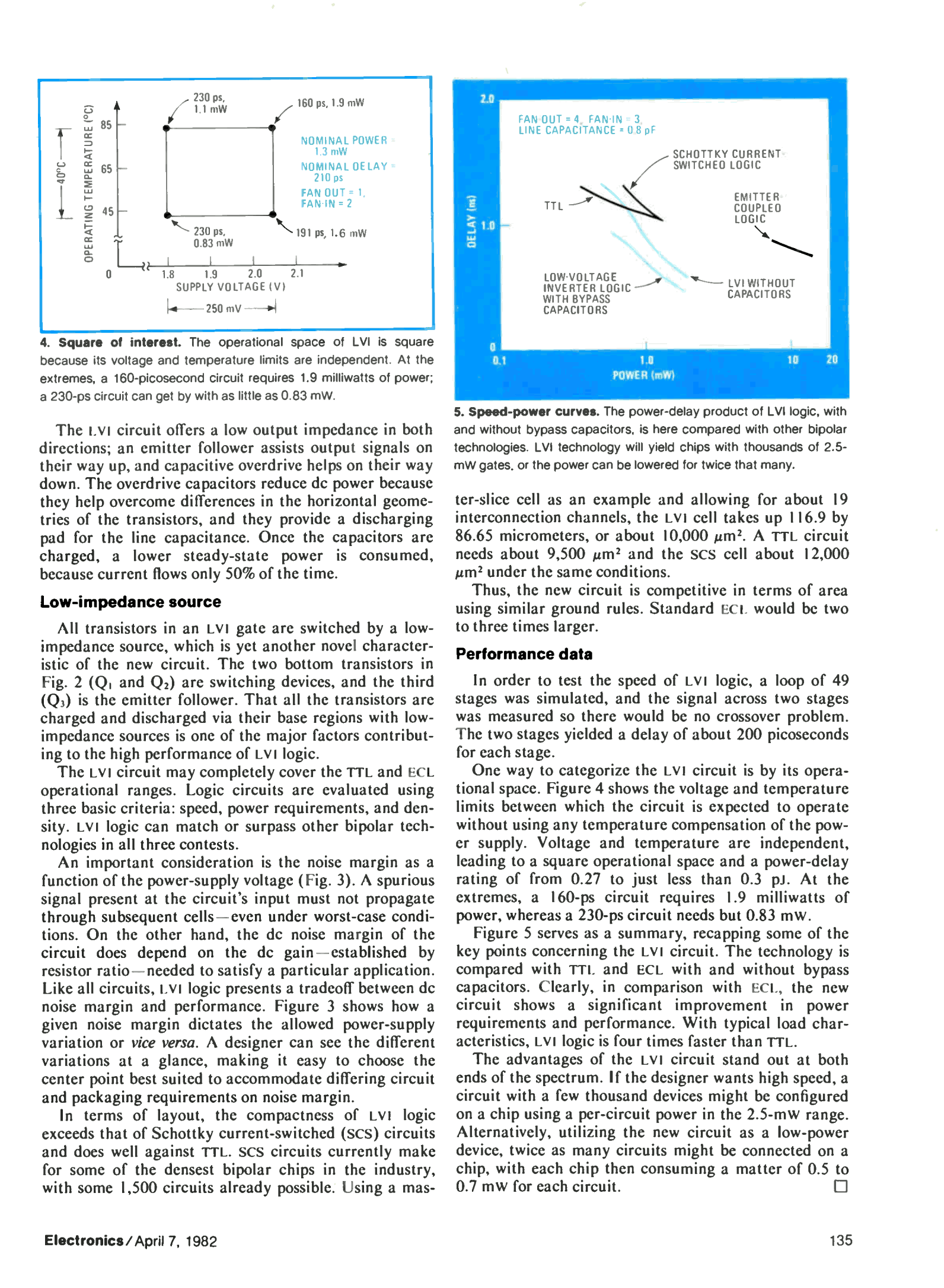
26. IBM's LVI (Low-Voltage Inversion Logic)
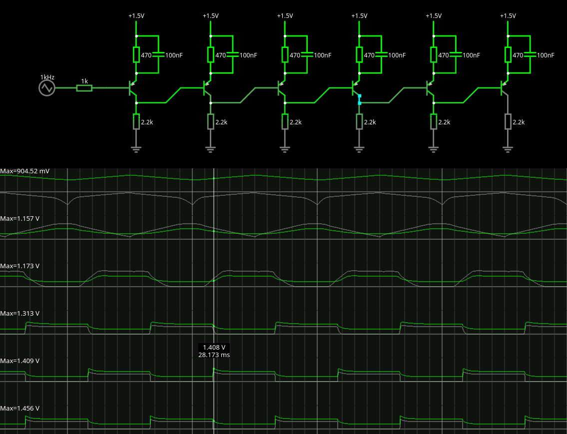
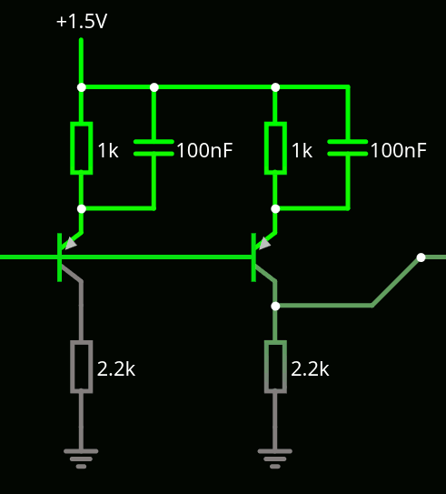
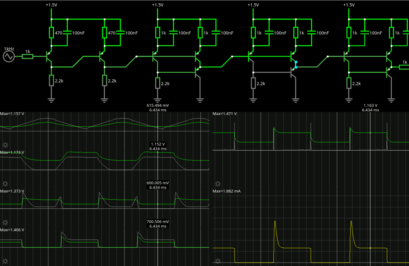
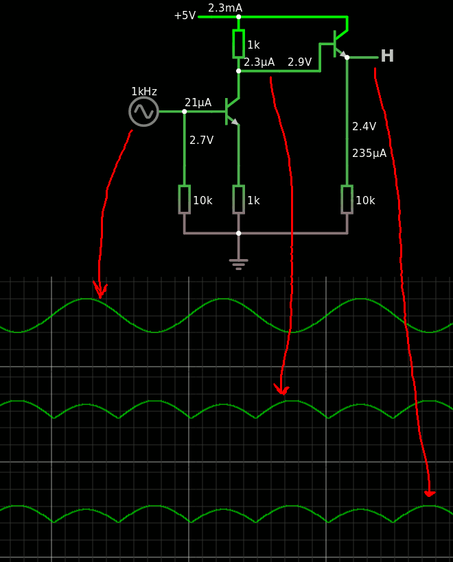
27. Reconstructing IBM's LVI (Low-Voltage Inversion Logic)
28. Attempting to design custom LVI inverters
.
.


 Al Williams
 Tim
Tim
(I posted a question but I think in the wrong area... try again!) I'm building a 16-bit tri-state program counter using 7400-family chips. I'm stuck with four 74HC161 4-bit counters and two 74HC241 8-bit buffers. Anybody know a way to reduce the chip count here, with TTL-level DIP devices? Need to increment, load, hold value & tri-state.