 Yann Guidon / YGDES
a few minutes of soldering bring the base capacitors to the board... and once again Tim's curves are confirmed !
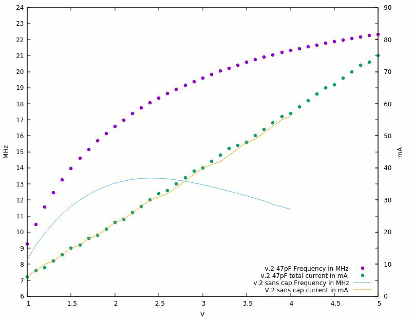
The data :
V     mA     MHz
1      6    9.263
1.1    8   10.481
1.2    9   11.560
1.3   11   12.456
1.4   13   13.268
1.5   15   13.974
1.6   16   14.592
1.7   18   15.166
1.8   19   15.692
1.9   21   16.156
2     23   16.603
2.1   24   16.985
2.2   26   17.381
2.3   28   17.731
2.4   30   18.056
2.5   32   18.360
2.6   33   18.634
2.7   35   18.899
2.8   37   19.150
2.9   39   19.386
3     40   19.617
3.1   42   19.828
3.2   44   20.036
3.3   46   20.223
3.4   47   20.406
3.5   48   20.585
3.6   50   20.750
3.7   52   20.906
3.8   54   21.057
3.9   56   21.191
4     57   21.322
4.1   59   21.435
4.2   61   21.552
4.3   63   21.666
4.4   65   21.771
4.5   66   21.877
4.6   68   21.976
4.7   70   22.073
4.8   72   22.163
4.9   73   22.251
5     75   22.337
The script :
set xlabel 'V'
set ylabel 'MHz'
set y2label 'mA'
set xr [1:5]
set yr [6:24]
set y2r [0:90]
set ytics 1
set y2tics 10
set key right bottom
plot "ringo9_2_47pF.dat" using 1:3 title "v.2 47pF Frequency in MHz" w points pt 7,  \
     "ringo9_2_47pF.dat" using 1:2 axes x1y2 title "v.2 47pF total current in mA" w points pt 7,  \
     "ringo9_2_sans.txt" using 1:3 title "v.2 sans cap Frequency in MHz" w lines, \
     "ringo9_2_sans.txt" using 1:2 axes x1y2 title "V.2 sans cap current in mA" w lines
Once again the capacitor is a simple yet very effective means to go faster, yet the power curve is not affected (in a meaningful, significant way). So the efficiency is much better than v1 :-)
At 5V the circuit easily reaches 22MHz, or 2.5ns per inverter !
But is it necessary to go THAT fast ? Where is the sweet spot again ? I don't think it's a good idea to run at 5V because the speed is only marginally better for a very significant increase in power draw (42mW/gate, or 1.8mW/MHz). So maybe 5V would be reserved for special cases and places that need a serious fanout.
- 2V : 46mW => 5.1mW/gate, or 0.3mW/MHz/gate
- 2.5V : 80mW => 8.8mW/gate, or 0.48mW/MHz/gate
- 3V : 120mW => 13.3mW/gate, or 0.68mW/MHz/gate
- 3.3V : 152mW => 16.8mW/gate, or 0.83mW/MHz/gate
- 5V : 375mW total, 42mW/gate, or 1.8mW/MHz
It would be wise to stay under the 1mW/MHz/gate, 0.5mW/MHz/gate would be even better but the fanout would be insufficient. The standard voltage 3.3V would be a good compromise but let's wait for the results with the other cap values and the diodes !
Anyway : Going from 2.5V to 3.3V brings only 10% more speed while the power almost doubles !
But what is the right capacitor value ?
the datasheet specifies < 4pF for the gate charge. So the capacitor must be higher than that to cancel the effect. So maybe 47pF ?
OTOH I saw a speed difference that is similar between 27pF (PCB v.1) and 47pF (PCB v.2) so there would be a diminishing return, which can only be spotted by plotting the V/F curve with various capacitances.
The smallest capacitors I have are 10pF so that's a good start. I can then add 18pF in parallel to give 28pF. Adding 47pF again will give another trace...
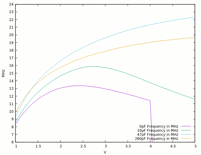
The results for 10pF are below :

From this graph, we can only suppose that the next increase would be to 220pF...
Meanwhile, the current graph has not changed so I don't show it anymore.
Testing with 280pF gives a pretty unexpected curve, but good to know anyway :
After a promising start at very low frequency, the 47pF curve is already winning at 1.4V. I now have to check at 100, 68 and 33pF if there is another local maximum...
The 100pF curve is disappointing : why is it worse than the 280pF ?
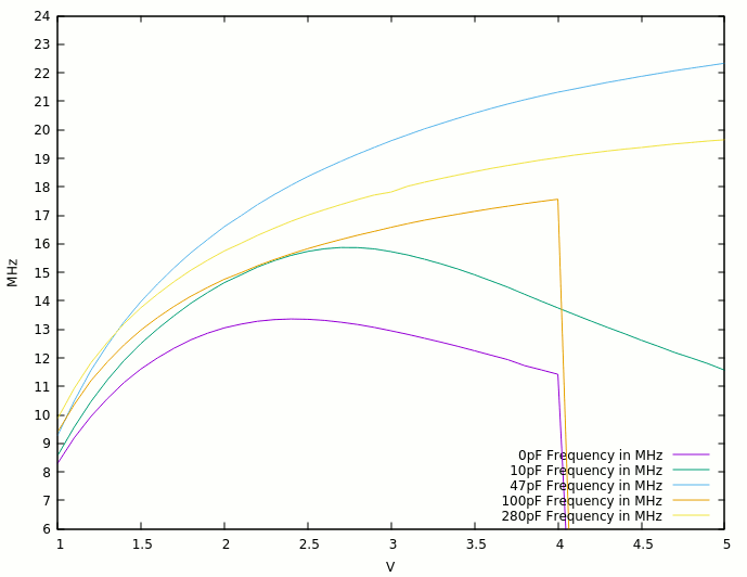
What is so special about the 47pF I tried ? Did I fry a part ?
Trying with 33pF caps shows interesting results as well, close to the 47pF.

Apparently the 2×33pF combination has a very light advantage up to 3.5V : that's still good to take and much better than other values.
Now trying 68pF gives a result very close to 2×33pf. So close that gnuplot almost mixes the colors, unless you zoom a lot.
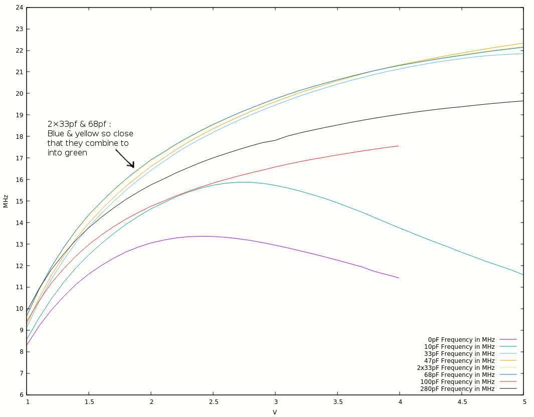
So 68pF wins by a tiny margin, but that's all I intended to find out :-)
The dataset :
1    8.292    8.563   9.116    9.263   9.623   9.653    9.391    9.863
1.1  9.191    9.57   10.316   10.481  10.858  10.900   10.358   10.927
1.2  9.942   10.464  11.384   11.560  11.938  11.955   11.197   11.826
1.3  10.576  11.237  12.276   12.456  12.821  12.861   11.865   12.551
1.4  11.140  11.913  13.089   13.268  13.627  13.663   12.461   13.204
1.5  11.609  12.501  13.792   13.974  14.320  14.363   12.974   13.756
1.6  12.001  13.014  14.410   14.592  14.924  14.961   13.416   14.239
1.7  12.344  13.485  14.979   15.166  15.477  15.517   13.810   14.678
1.8  12.636  13.918  15.509   15.692  15.988  16.029   14.163   15.077
1.9  12.867  14.294  15.981   16.156  16.437  16.480   14.473   15.428
2    13.053  14.639  16.427   16.603  16.877  16.916   14.758   15.752
2.1  13.182  14.911  16.820   16.985  17.226  17.265   14.988   16.019
2.2  13.286  15.19   17.219   17.381  17.599  17.634   15.234   16.301
2.3  13.343  15.414  17.566   17.731  17.932  17.959   15.449   16.55
2.4  13.364  15.595  17.885   18.056  18.243  18.268   15.647   16.789
2.5  13.354  15.735  18.189   18.360  18.538  18.559   15.832   17.006
2.6  13.317  15.827  18.465   18.634  18.803  18.818   15.999   17.197
2.7  13.253  15.874  18.735   18.899  19.066  19.076   16.155   17.38
2.8  13.170  15.870  18.990   19.150  19.309  19.307   16.302   17.555
2.9  13.068  15.822  19.228   19.386  19.539  19.531   16.441   17.715
3    12.952  15.73   19.457   19.617  19.756  19.749   16.582   17.816
3.1  12.826  15.610  19.671   19.828  19.955  19.949   16.710   18.022
3.2  12.689  15.463  19.884   20.036  20.141  20.140   16.831   18.165
3.3  12.552  15.3    20.072   20.223  20.312  20.311   16.939   18.294
3.4  12.408  15.121  20.251   20.406  20.475  20.472   17.041   18.415
3.5  12.253  14.92   20.423   20.585  20.631  20.630   17.140   18.531
3.6  12.097  14.701  20.589   20.750  20.786  20.779   17.234   18.645
3.7  11.938  14.481  20.734   20.906  20.927  20.921   17.322   18.75
3.8  11.729  14.235  20.884   21.057  21.062  21.060   17.410   18.85
3.9  11.580  13.99   21.016   21.191  21.185  21.182   17.489   18.942
4    11.426  13.753  21.136   21.322  21.300  21.296   17.565   19.029
4.1   0      13.52   21.248   21.435  21.406  21.400    0       19.114
4.2   0      13.288  21.352   21.552  21.506  21.500    0       19.187
4.3   0      13.066  21.457   21.666  21.608  21.590    0       19.26
4.4   0      12.85   21.537   21.771  21.702  21.681    0       19.325
4.5   0      12.62   21.617   21.877  21.797  21.766    0       19.38
4.6   0      12.41   21.690   21.976  21.882  21.851    0       19.446
4.7   0      12.19   21.748   22.073  21.966  21.933    0       19.505
4.8   0      12      21.790   22.163  22.035  22.010    0       19.558
4.9   0      11.8    21.825   22.251  22.105  22.077    0       19.608
5     0      11.57   21.850   22.337  22.174  22.144    0       19.653
and the gnuplot script :
set xlabel 'V'
set ylabel 'MHz'
set xr [1:5]
set yr [6:24]
set ytics 1
set key right bottom
plot "ringo9v2_0-10-33-47-66-68-110-280pF.dat" using 1:2 title "   0pF Frequency in MHz" w lines, \
     "ringo9v2_0-10-33-47-66-68-110-280pF.dat" using 1:3 title "  10pF Frequency in MHz" w lines, \
     "ringo9v2_0-10-33-47-66-68-110-280pF.dat" using 1:4 title "  33pF Frequency in MHz" w lines, \
     "ringo9v2_0-10-33-47-66-68-110-280pF.dat" using 1:5 title "  47pF Frequency in MHz" w lines, \
     "ringo9v2_0-10-33-47-66-68-110-280pF.dat" using 1:6 title "2x33pF Frequency in MHz" w lines, \
     "ringo9v2_0-10-33-47-66-68-110-280pF.dat" using 1:7 title "  68pF Frequency in MHz" w lines, \
     "ringo9v2_0-10-33-47-66-68-110-280pF.dat" using 1:8 title " 100pF Frequency in MHz" w lines, \
     "ringo9v2_0-10-33-47-66-68-110-280pF.dat" using 1:9 title " 280pF Frequency in MHz" w lines
The conclusion is : below 3.5V, 68pF is the chosen value. 47pF wins at higher voltages.
47pF still could pop up again for fanout more than 1. In this case, it might get some more help if the pull-up resistor is tied to a higher voltage.
And let's not forget : ample decoupling !
But this is not the end. We should now investigate the clamp diode's effect... See you in another log !
Discussions
Become a Hackaday.io Member
Create an account to leave a comment. Already have an account? Log In.
Very interesting results with the different caps. Seems that this is quite a sensitive optimization parameter. Would make sense to do some simulations.
Btw, I always added one additonal inverter as output buffer, so the loading on the ringo is not defined by the scope or anything else I attach.
Are you sure? yes | no
Hi !
Yes I noticed this difference... But with proper probing, the load of the tip is comparable or less than a second transistor base. I suppose.
Or we could use 50 ohms in series with Rc :-)
Are you sure? yes | no