 Yann Guidon / YGDES
Discussions on the chat with @Tim and his reseach into weird latches made me look back at my MUX-based latch. The early idea was not working but later revisions did, once I created a fully functional MUX2.
So here is a new version :
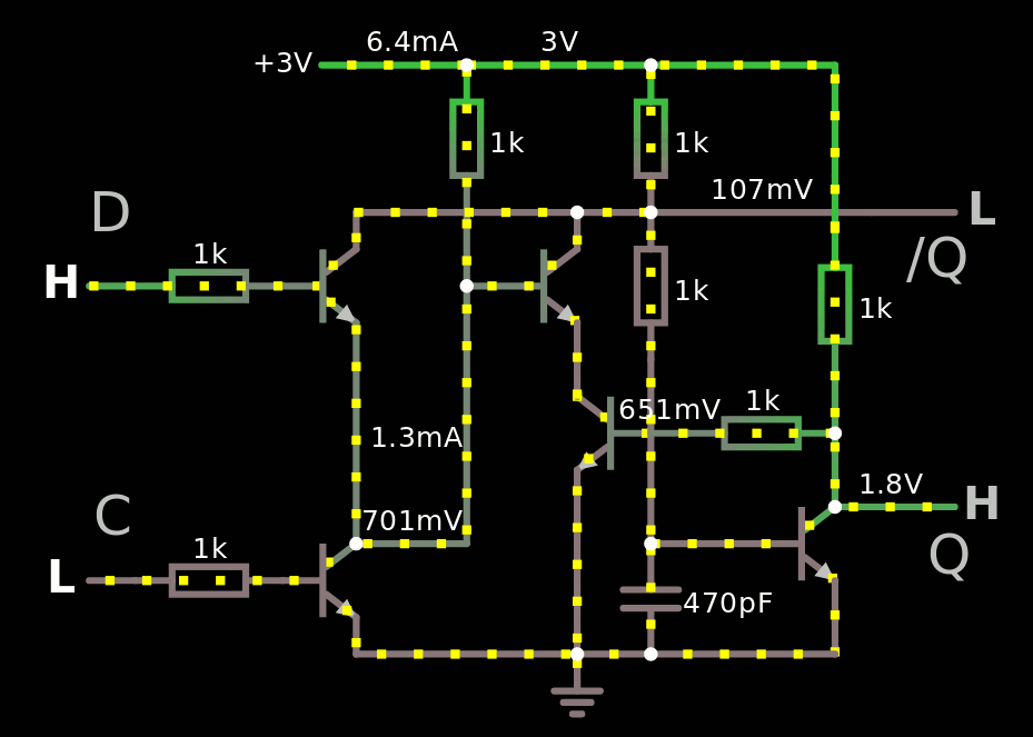
This one works down to 2V. It uses the same values for all resistors, it has a /Q output as well, a single-phase clock input, and only 5 transistors.
So far there are 5 transistors but for a whole register, the clock transistor can be shared among several bits.
At one point, I had to add a 1G resistor to prevent totally bonkers behaviour of the simulator between the two PN junctions of the transistors in series, ignore it for real circuits. In rare cases however, Falstad indicated 25GV at that node...
This time, I understood that there is one case that looks wrong but has no real effect on the circuit : when C is low and Din is high and feeds current into the /Q node, but it does not matter. In previous versions I added diodes to prevent current from flowing back but when absent, the working supply voltage can go lower and the noise immunity is better (or it can dissipate less power).
The /Q output might not be required. In this case, the 1K resistor that feeds the base of the output transistor could be omitted. This would also speed the circuit up a bit.
At some points I have problems with Falstad's sim (how surprising !) because the circuit wouldn't want to hold the High state on Q. I added a 470p capacitor to hold a bit of charge during the clock transition but later retries (and a full screen refresh) work without it... The value is approximate and the transistors' inherent capacitances would normally do the trick and add the tiny delay. Of course, a full simulation with xSPICE will work better :-)
Of course Falstad is a bit buggy but in practice, it's a lot like in real circuits, which are not perfect either. If you can make your circuit work in many conditions in Falstad's sim, the real circuit has good chances to work in real life.
The next step is obviously to create a DFF with a pair of these cells but in practice, timing is everything and with discrete computers, the clock strobe can be made very short, or successive latches can be strobed by clock signals with a little delay...
Discussions
Become a Hackaday.io Member
Create an account to leave a comment. Already have an account? Log In.