 Nolan Moore
Welcome!
This project was brewing in my mind, making small progresses here and there for months before I finally got the initial prototyping started and posted this project here on Hackaday.io. Having had so much time to review what's been done and figure out where I want to go, I hope to present to you, dear reader, full and concise accounts of said progress. For this initial log, I’ll be covering some of the ideas, planning and preparation that went into the project. It all started with...
Crazy Ideas And Delusions of Grandeur
If you’ve read the details in the project intro, you might know that I have some mad ideas for the Power Glove. Controlling anything and everything in order to rule the world might be a tad unrealistic for such a project, but mainly I've been working on it as a way to take my mind off of work and potentially transition onto something even greater.
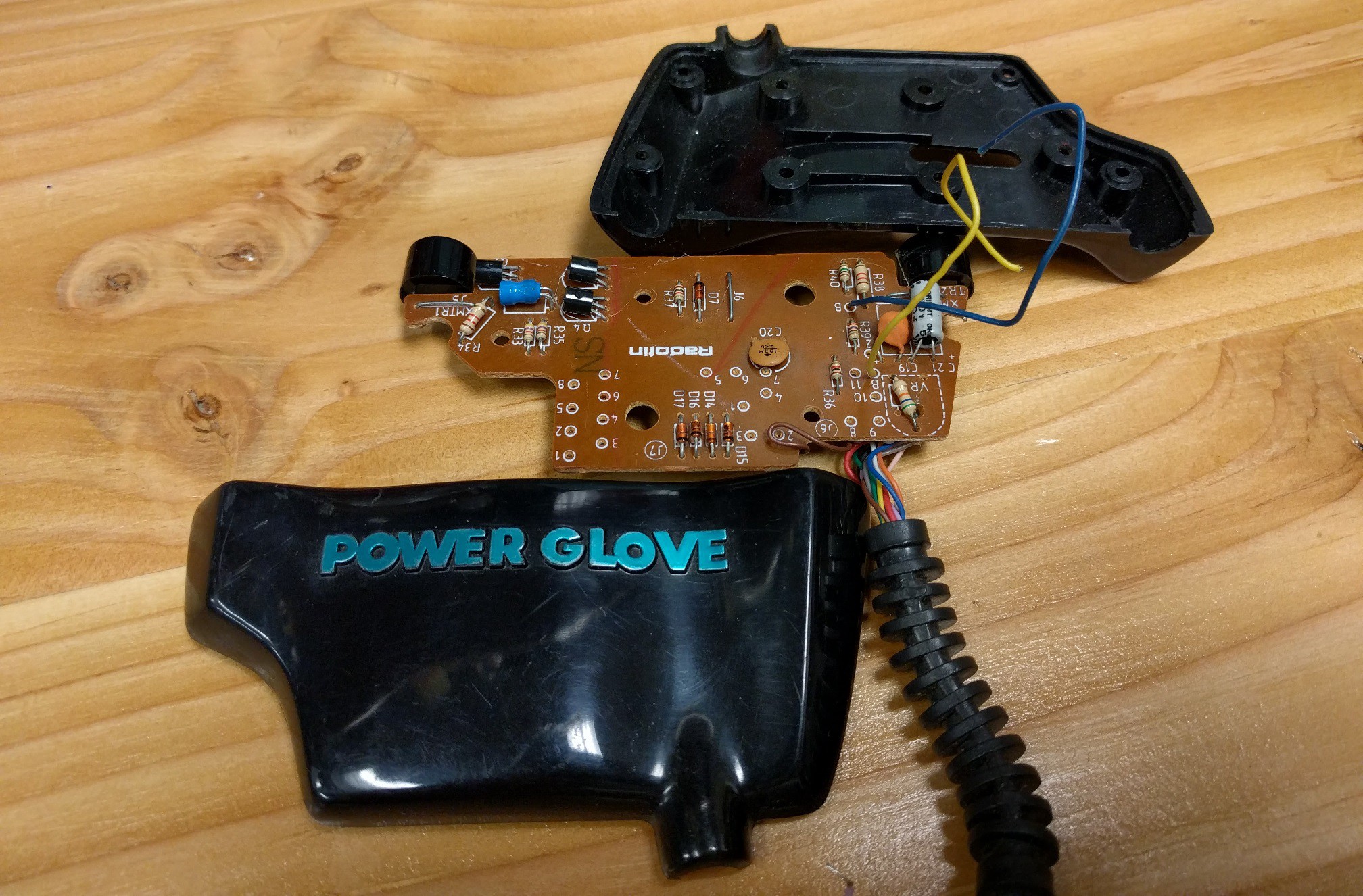
I knew that I wanted to modify the glove in such a way that the original aesthetic would be maintained. Sure it was a novelty project, but I wanted something clean I could show off, no hacked togetherness, no wires hanging out (excluding the prototypes of course). After opening it up and getting a good look at the boards and the limited spacing, I knew I would have to create something original to fit everything in. Preserving the boards was not an option.
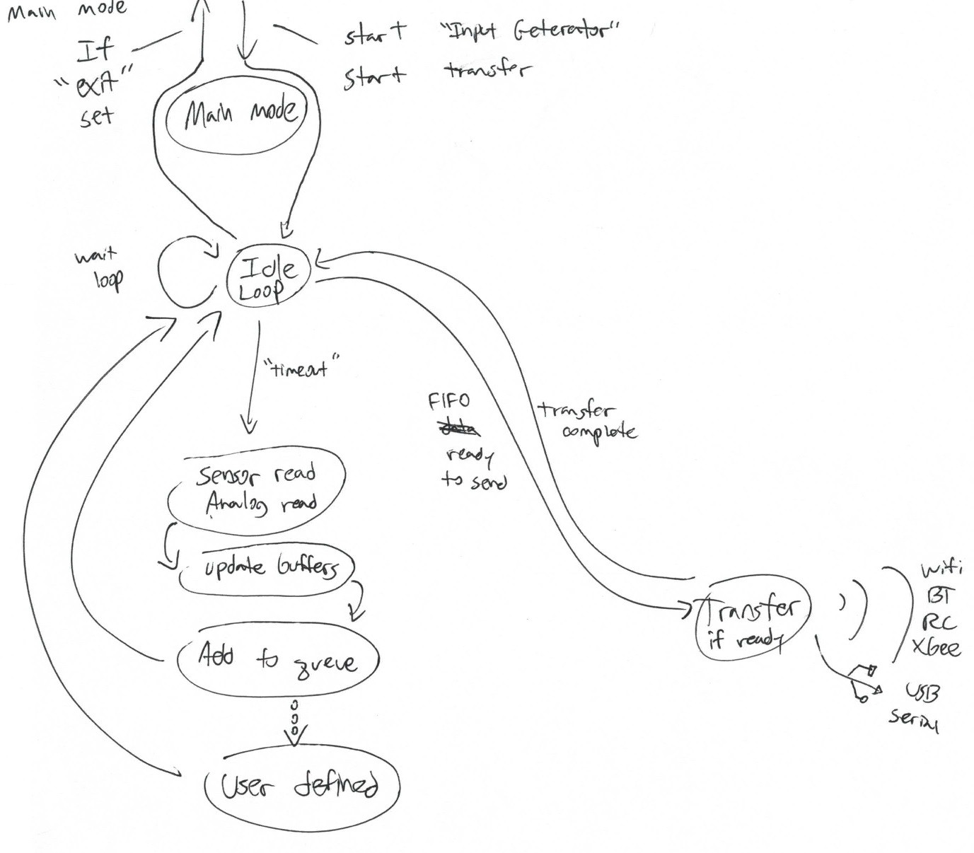
I spent a large amount of time doing conceptual work for the project, putting together feature wishlists, drawing up ideas for gesture controls, creating state flow charts for the code... Much of this was lost after moving last winter, but some sketches remain.
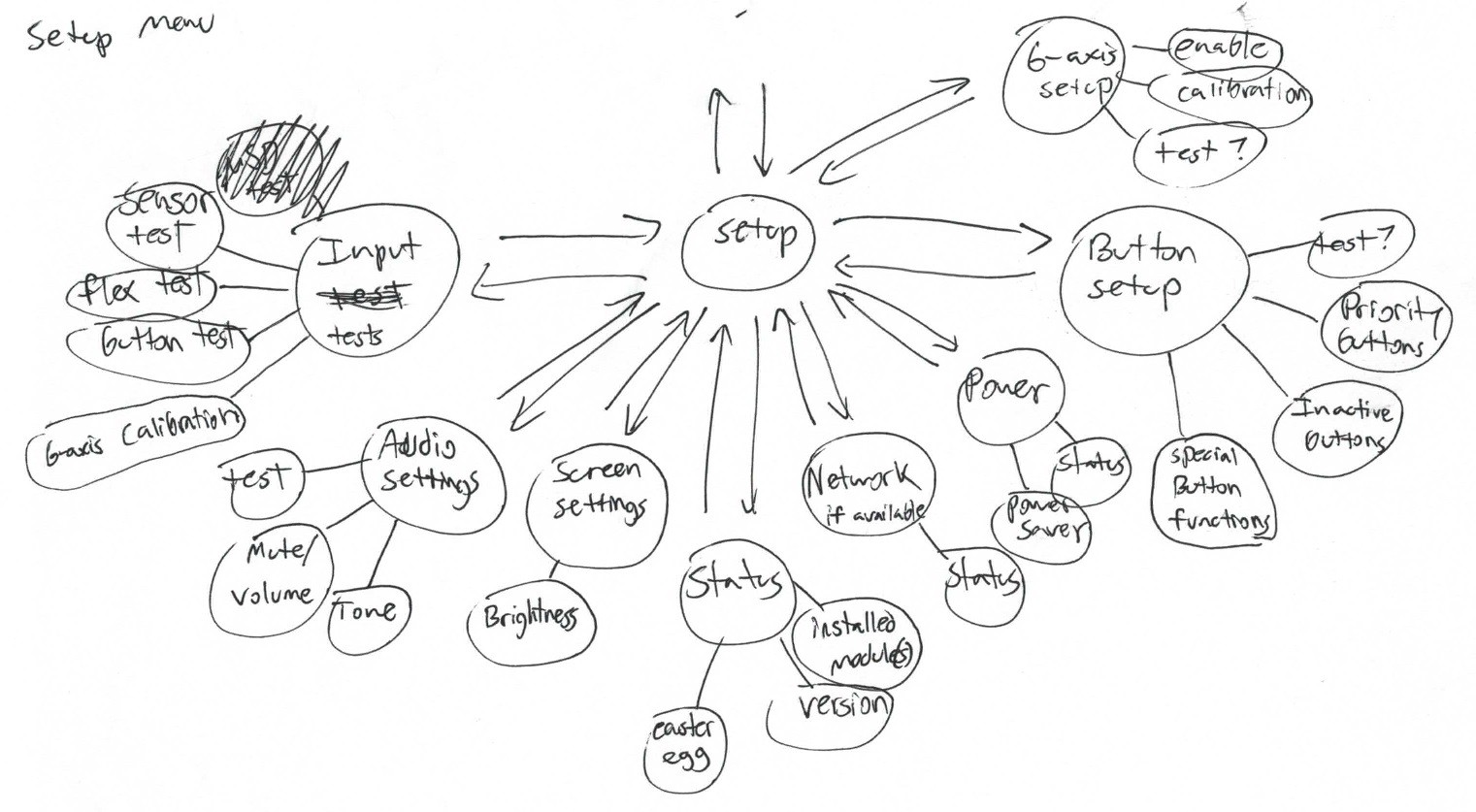
Plenty of features were planned for the glove, and though many were scrapped for the initial prototype, they yet may be realized down the line. Some ideas just didn't make the cut due to design restrictions. One idea involved putting a Nokia phone display (later an OLED screen) in the sensor enclosure to give the user a menu for setting up the glove and monitoring data. Due to the glove's lack of visual feedback, this would have been quite nice, but the idea was put on hiatus in favor of retaining an unmodified look. Eventually, concepts gave way to requirements, and I started to put together what I would need to make the project a reality.
Choosing the Main Components
Main board
For the microcontroller in the main board, I wanted to use the Arduino Zero design because it was the hip new dev board in town and it would give me some practice designing an ARM Cortex-M0+ device. As my programming had become a bit rusty, I hoped to forgo Arduino altogether and do some embedded programming instead. For prototyping purposes though, I decided to use what I had on hand, a Teensy 3, and a Teensyduino setup for ease of testing.
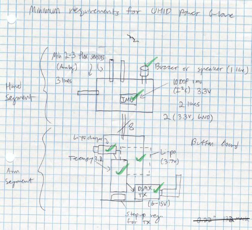
Stemming from my work in quadcopters, the earliest idea for wireless communications was to use a DIY RC transmitter to control RC devices. The idea transformed into using interchangeable expansion cards to provide RC, Wi-Fi, Xbee, Bluetooth and other protocols by simply switching out the cards and configuration profile for the new device. This could be accomplished through something as simple as Xbee style boards. For now, the initial prototyping project (controlling a Parrot AR.Drone)would use an ESP8266 module, specifically an Adafruit Huzzah, for Wi-Fi communication.
In order to keep the glove wire-free, a single cell LiPo battery and on-board charger would be used to power the system. A step-down/up converter would be used to provide 3.3V to the system. Pololu offers a wide range of switching regulators, making prototyping fairly convenient.
Sensor board
As many gamers now know, the Power Glove didn’t quite live up to the massive hype generated by commercials and a certain infamous movie. The TV receiver frame and the glove’s ultrasonic emitters would have to go. In their place, a 6 degree of freedom (6DoF) IMU would provide motion measurements. I had a couple 10DoF (a bit overkill really) AltIMU-10 boards from Pololu around for prototyping, but the final board would implement the sensors directly.
Unfortunately, ditching the ultrasonic emitters in the glove would leave gaping holes in the enclosure. This could be remedied by replacing the emitters with RGB LEDs or speakers for some cool effects. Another option would be to continue using those areas for sensing purposes.Specifically, an IR transmitter (LEDs) and receiver could be used to control devices or allow the glove to act as a pointing device, similar to the Wii remote. These will be heavily considered in future prototypes.
The flex sensors in the glove were a bit of a gamble. After some testing, I found that 27 years takes a toll on such components, and their readings certainly didn’t get better age. I would have to replace them with new sensors from Spectra Symbol (supposedly the same company that made the originals, but I haven’t found any concrete proof yet).
With the components for prototyping chosen and acquired, I was ready to begin creating my replacement board. In hindsight, I should have actually modified the glove and created my initial prototype before I sat down to design a new board from scratch, but at the time I was too excited by theose ideas of grandeur. So, with the board completely accessible, I began taking measurements.
Taking Board Measurements
Main Board
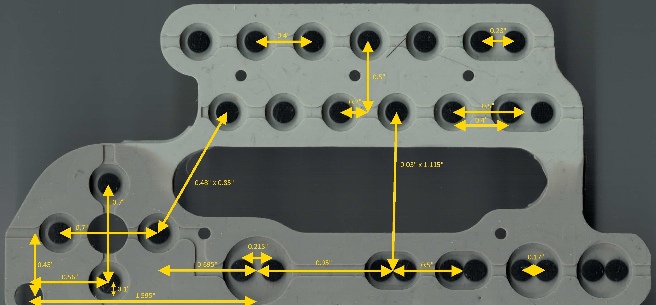
I used calipers to capture the easier measurements, such as edges and mounting holes, but I found locating the exact dimensions of the conductive button pads to be something of a challenge. I started desoldering parts from the board in an attempt to get a flat scan of the button side, but with each scan the board was always slightly tilted, giving bad measurements.
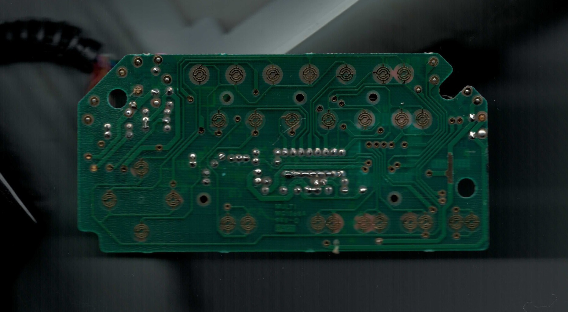 After multiple annoying attempts to get a clean flat scan, I had the so-simple-it's-genius idea to scan the button pads instead. Numerous digital measurements in Paint.net later and the board dimensions were done.
Scanning the main board itself did have its benefits though. I used the flattest scan I had to create footprints in Eagle (and later KiCad) for the PCB button pads.
Sensor board
Replicating the sensor board would be a little more challenging, and I decided to forgo measuring it until I finished the main board. Instead, a small board utilizing the central mounting holes was created to hold an IMU and the necessary connections to the flex sensors and the main board.
Next Steps
With the measurements ready to go, I was finally ready to start on the board design. In the next log, I'll detail the events leading up to the initial designs of both the main board and the sensor board. See you then!
Discussions
Become a Hackaday.io Member
Create an account to leave a comment. Already have an account? Log In.