 Nolan Moore
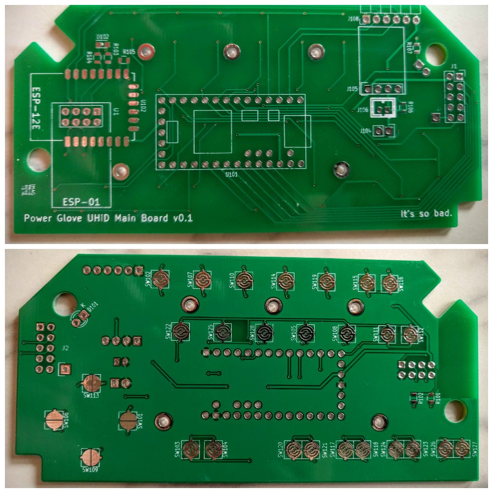
This is the big one! After a few weeks, both boards are finally here! Small disclaimer though: the control board actually arrived a couple weeks prior to the sensor board, but since I found myself still trying to catch up on logs, I ended up waiting to write this one until both boards had arrived and been tested. As you can see in the photo below, they came from two different board houses. The sensor board on the left was produced by Seeed Studio, and the control board on the right (dubbed the Main Board on the silkscreen) was made by Accutrace (a.k.a. PCB4U.com).
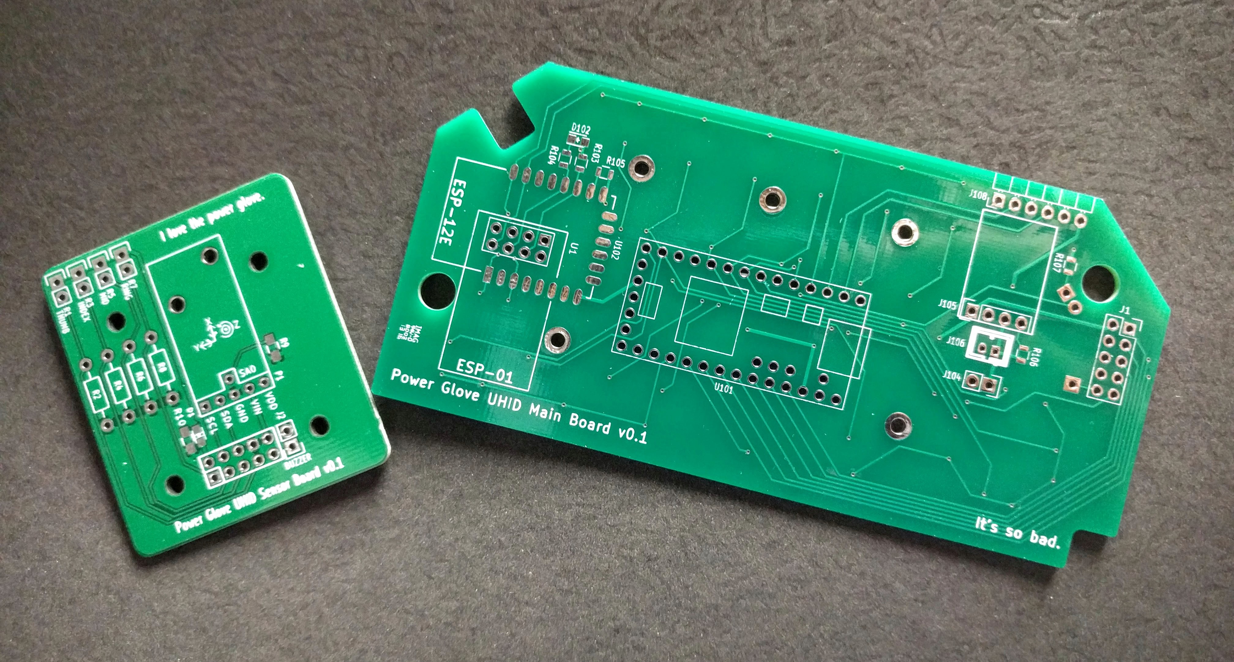
Both boards are of good quality, but due to a much sharper silkscreen and a deeper color (and better quality) soldermask, the control board totally took the cake. I'd ordered boards from both houses previously for work projects, so I knew what sort of quality I would getting on these ones. Perhaps I'll do a separate post elsewhere one of these days on differences between various board houses...
But anyway, let's get these boards installed!
The Control Board
To install this board, I'll be replacing the modified board in the old glove (not the new one covered in the previous log), but first I've gotta get the board assembled. There are relatively few components, making this a fairly quick procedure. This is fortunate as there were barely any photos taken during the assembly and testing of the new board (I mean, there's not too much going on just yet). I do have this mini collage though: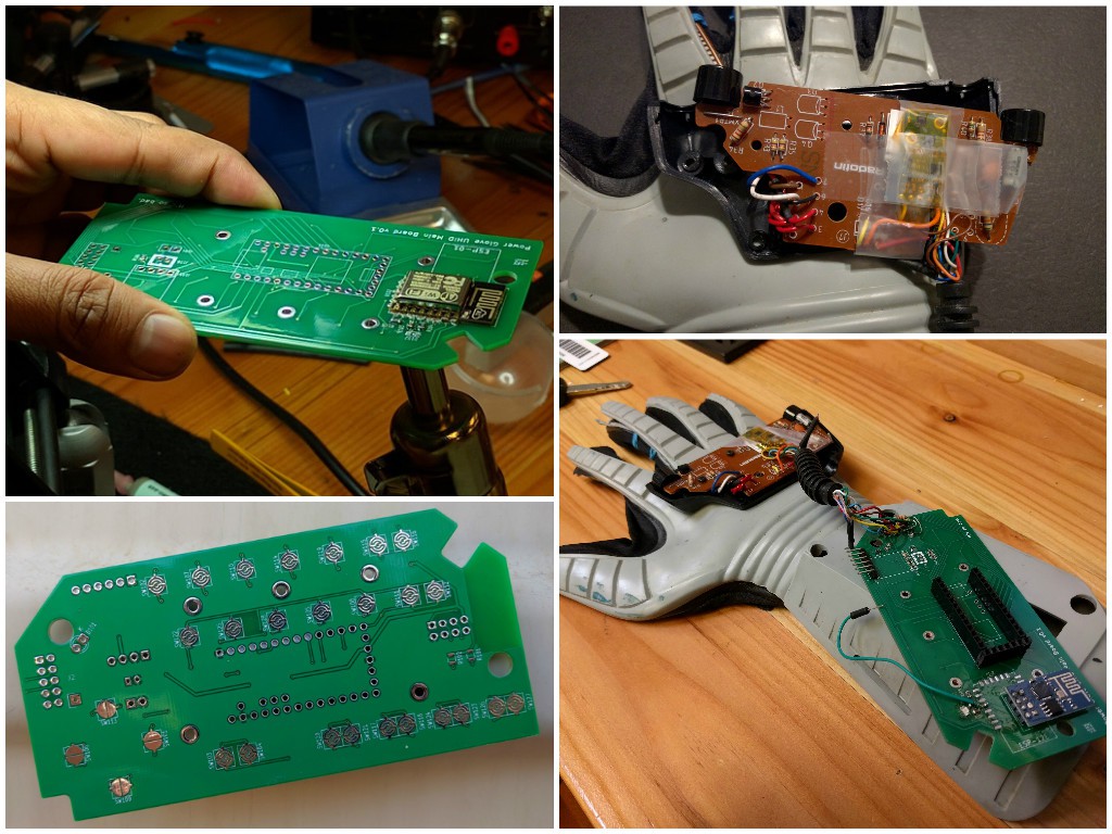
Not shown in the photos above, the back half of the enclosure was modified to fit the various components that proved to be a bit too tall to fit within the case. Using a Dremel, a hole for the Pololu voltage regulator and serial header was made along the top (narrower long side) of the case. The ESP-01 was also a bit too high, but in the interests of not cutting too many holes, was left alone (the final testing unit may have had more tape holding it together than was envisioned). To put it bluntly, besides the planned ESP-12E and the top-side LED, nothing would've properly fit into the case without modification. Achieving a slimmer profile will require future boards to use more SMD components and preferably no through-hole modules.
A few other expected issues arose during testing. I'll list them out here with the lessons learned in bold.
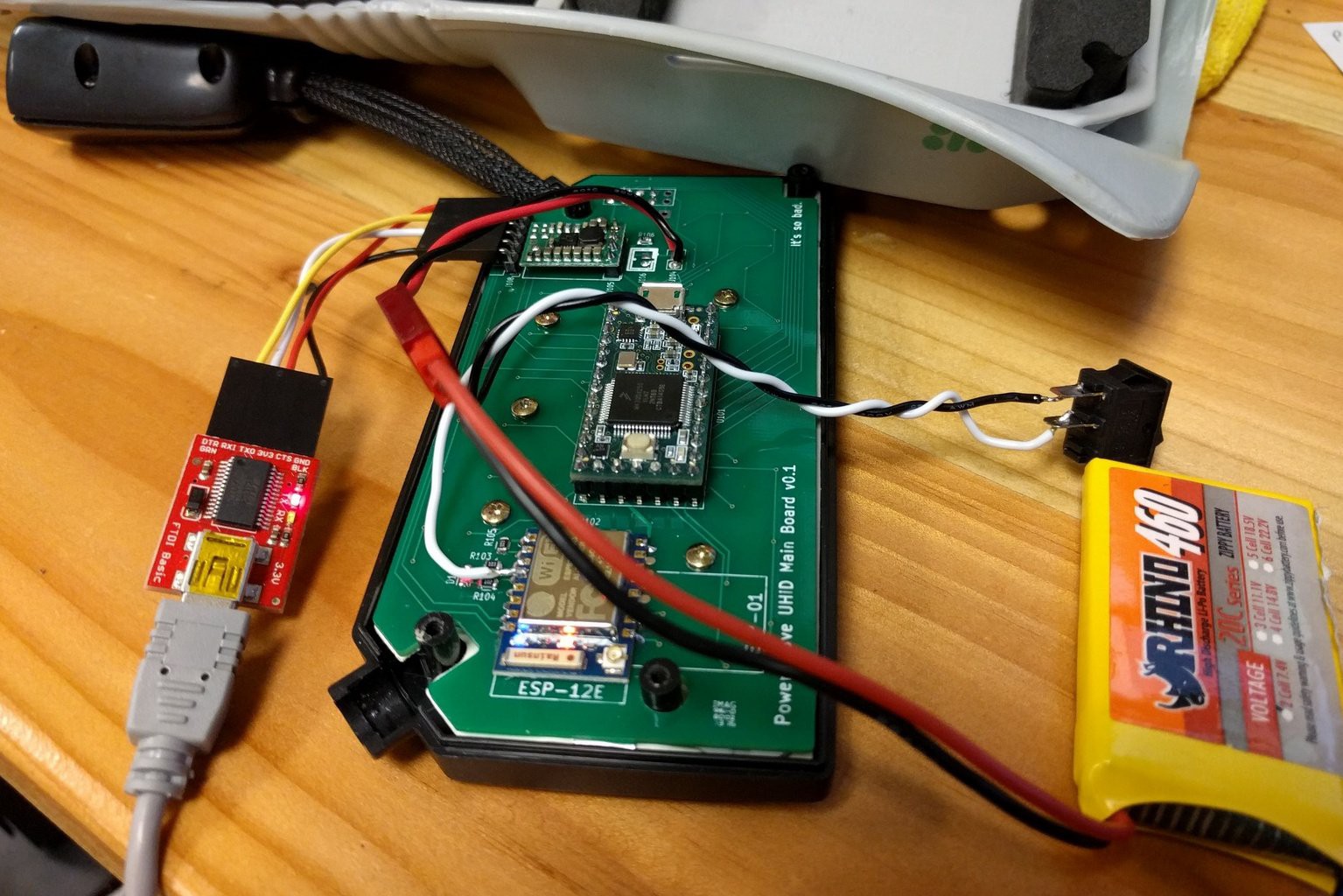
- Don't forget your required components. As mentioned in a previous log, I had forgotten to add reset and bootloader buttons to the ESP sub circuit. After soldering a jumper wire to the ESP's GPIO0 pin directly to be able to set bootloader mode during a hard reset, programming the ESP became only a slight PITA.
- Plan ahead. Though not necessarily a design issue, the voltage dividers needed for the glove's flex sensors still had no designated footprints. Those resistors would be found on the sensor board. I ended up soldering the resistors to the incoming wires from the sensor board directly. Ugly, but sufficient.
- You get what you pay for. A final issue presented itself in the actual components. As the first picture in the collage shows, I originally used an ESP-12 WiFi module. Unfortunately, this module, as well as another I replaced it with soon after, were sourced from what I believed to be a somewhat respectable international distributor on Aliexpress. After getting them soldered to the board, I found them to be DOA as they refused to respond to firmware upload attempts. In the end, I replaced both of them with a working ESP-01 module (not exactly less sketchy, got it on eBay from China, but thank goodness I put that extra footprint in there!).
Board issues out of the way, there were a couple necessary changes to make to the Teensy's firmware. A new configuration was set for the board's new keypad layout, and pin definitions were updated to match the new pinout.
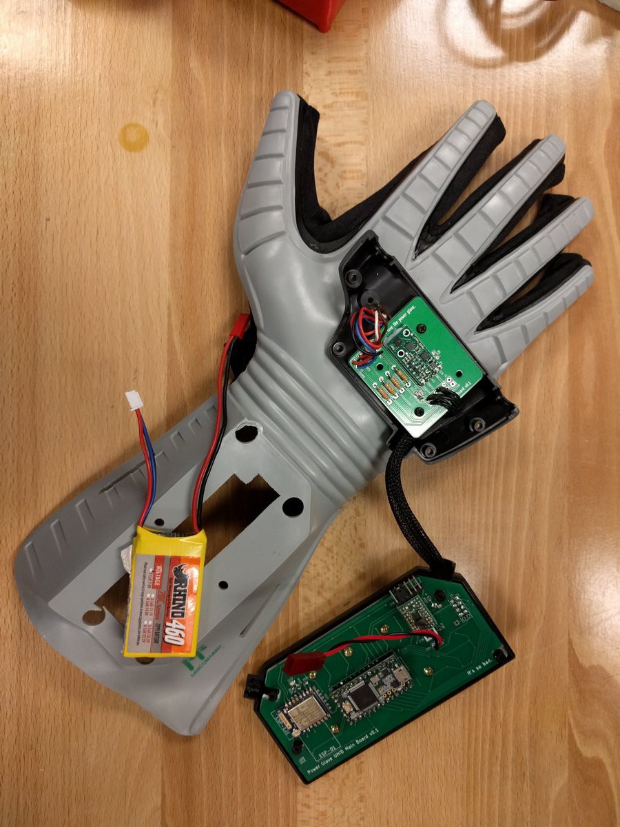
With the glove finally ready for use, a single cell Li-Po was connected to the control board and hidden in the gauntlet underneath the enclosure. With the USB battery pack and previous mess of wires gone, the glove was finally properly wireless! And due to minimal changes in the firmware, everything functioned as expected. Ready for the next step!
The Sensor Board

As mentioned in the intro, the sensor board arrived a few weeks after the control board, meaning that everything so far had been tested and was working properly. Thanks to the small number of components, this board would be much quicker to implement.

And... we're done. Easy, right? This one's been installed in the brand new glove I logged about previously!
One thing though, see those voltage dividers right there? The ones with the 33k ohm resistors? I made a bit of a mistake; I meant to go with 330k resistors.
Utilizing the wires I'd soldered to the new (original) sensor board, I found the values of the sensors to hover around 200k when relaxed and 450k with fist closed. With that range, 330k ohm resistors would have given a range of to 1.396V to 2.055V, a 0.659V range or about 205 values. Using 33k ohms gave a usable voltage range of about 0.225V to 0.467V, a 0.242V range or only 75 values at 3.3V. Not to worry though, I went back and swapped them out later, after realizing my mistake during testing.
Also, though the IMU was rotated counterclockwise, there was no need yet to update the Teensy firmware. At this point, the "protocol specs" still were and are not defined, and I would be correcting for the change on the ESP end.
Because the top half of the enclosure still had the speaker/piezo attached, I chose to instead use the enclosure from the old glove, the first sign of it becoming a Frankestein's-monster-like monster.
Assembling Another Control Board
Assuming testing went well, the boards used would essentially be the final prototypes. I decided to assemble a new control board that would be cleaner and fit properly in the enclosure (to the best of its ability).
I attempted to desolder the switching regulator from the old board but accidentally chipped a tiny piece off of the module's inductor, rendering it useless. After acquiring a new one, I made sure it worked and got it installed. To keep things on the short side, I picked up an ESP-07 module from the Hackaday Store (quality assured!) to replace the tall ESP-01, and the Teensy was soldered directly this time.
Eschewing the JST PH header (for the single cell Li-Po) in favor of a JST RCY wired connector, allowed more flexibility in the battery situation and let me use a 2 cell Li-Po with that connector already attached. I also attached a bootloader switch (and created a custom FTDI adapter) to make programming the ESP easier.
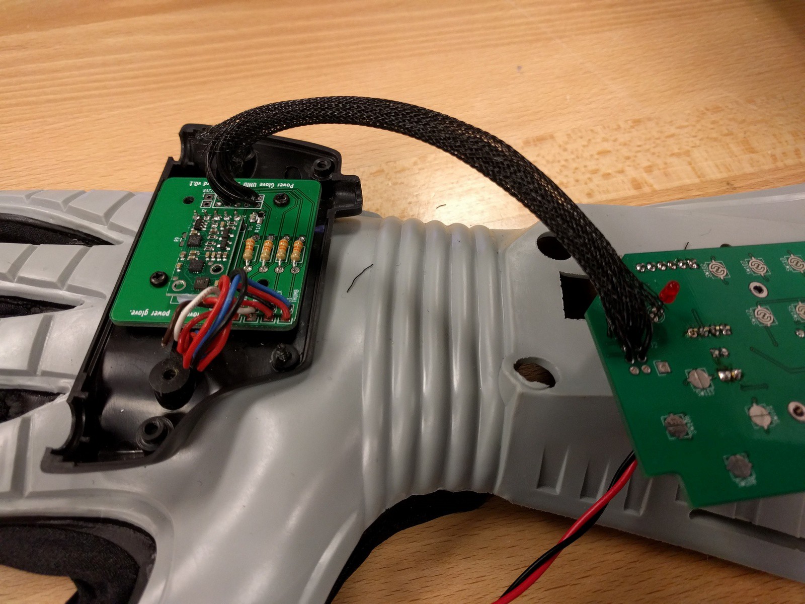
I didn't want to have to deal with the original crimped wire bundle this time around, so I twisted 8 wires together to create the board-to-board link and sheathed them with flexible braided wrap. Yes, I would be diverging from the mantra about maintaining the original look that I'd mildly stuck with up to this point, but the result actual looked quite good. As the wires were all black, a fair amount of continuity testing was in order.
The new board was installed in the front panel of the new glove, but I'd be using the old back panel to avoid making cuts in the untouched new one.
All in all, this iteration was shaping up nicely. With the two boards now connected, both were properly tested and found to work perfectly. It was time to reassemble everything.
The Finale
Yeah, I know this one's an earlier picture and missing the bootloader switch, shh!!
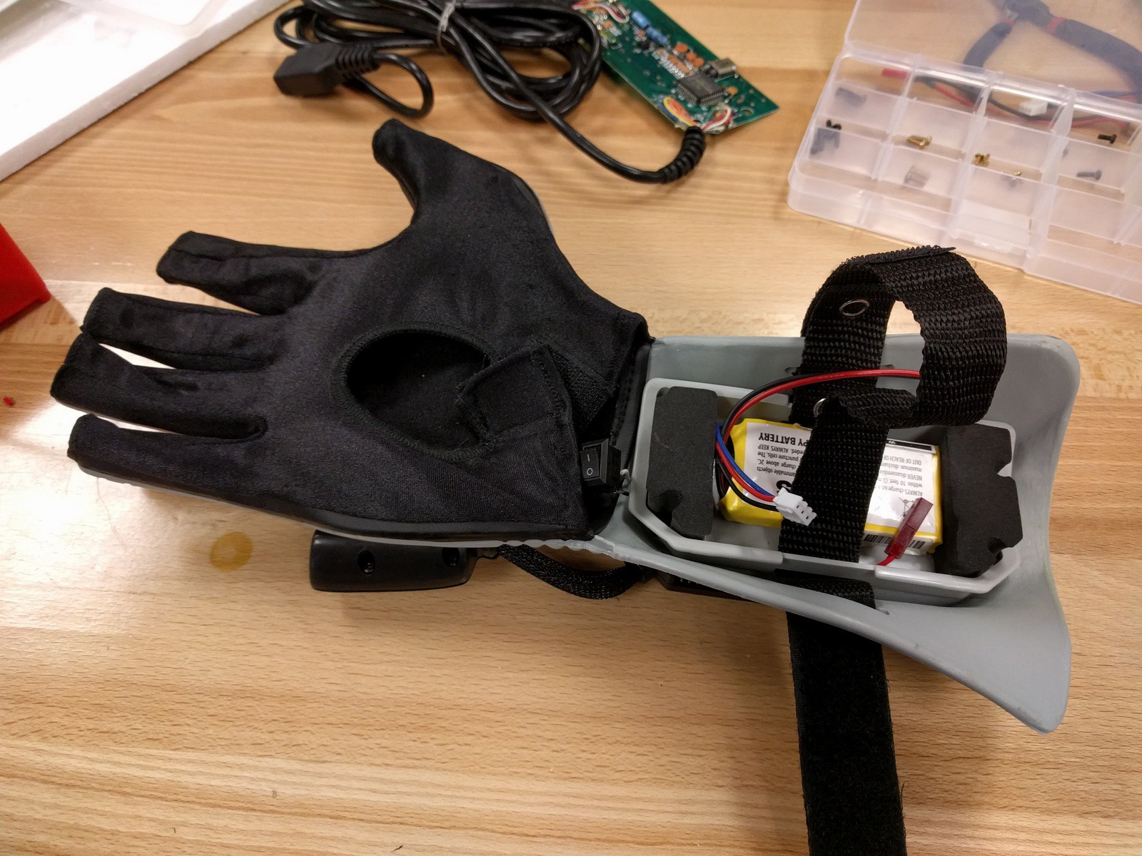
Enclosure and arm buffer thing back in place, Li-Po battery ready to go ! Those soulless eyes... It truly is a monster. For now...

Time to play.
And there you have it. The revamped Power Glove UHID, Mk I.
With the glove finally complete, I'll be putting more time into the actual HID component. The glove only utilizes WiFi at this time, but my goal is to find a control standard that I can follow (good) or create my own (bad) that works across as many communication mediums as possible. In the meantime, I'll probably start with setting the Teensy up as USB game pad. Even better, configuring the glove as a MIDI controller (a la Imogen Heap's Mi.Mu Glove)!
The next version of the board will likely feature Bluetooth as well as a cleaner board design with fewer through-hole parts and modules as mentioned earlier. SMD parts will leave me with much more room for components, a boon on a board with essentially a single usable side. Hopefully I'll even be able to add in that "expansion port" as well for future connectivity.
Stay tuned! Wicked awesome video coming soon!
Discussions
Become a Hackaday.io Member
Create an account to leave a comment. Already have an account? Log In.