Close
0%
0%

ESP8266 lamp/outlet control

A simple project using a esp8266-01 that will turn an outlet on and off.
With optional WEMO support for control with amazon alexa

Similar projects worth following
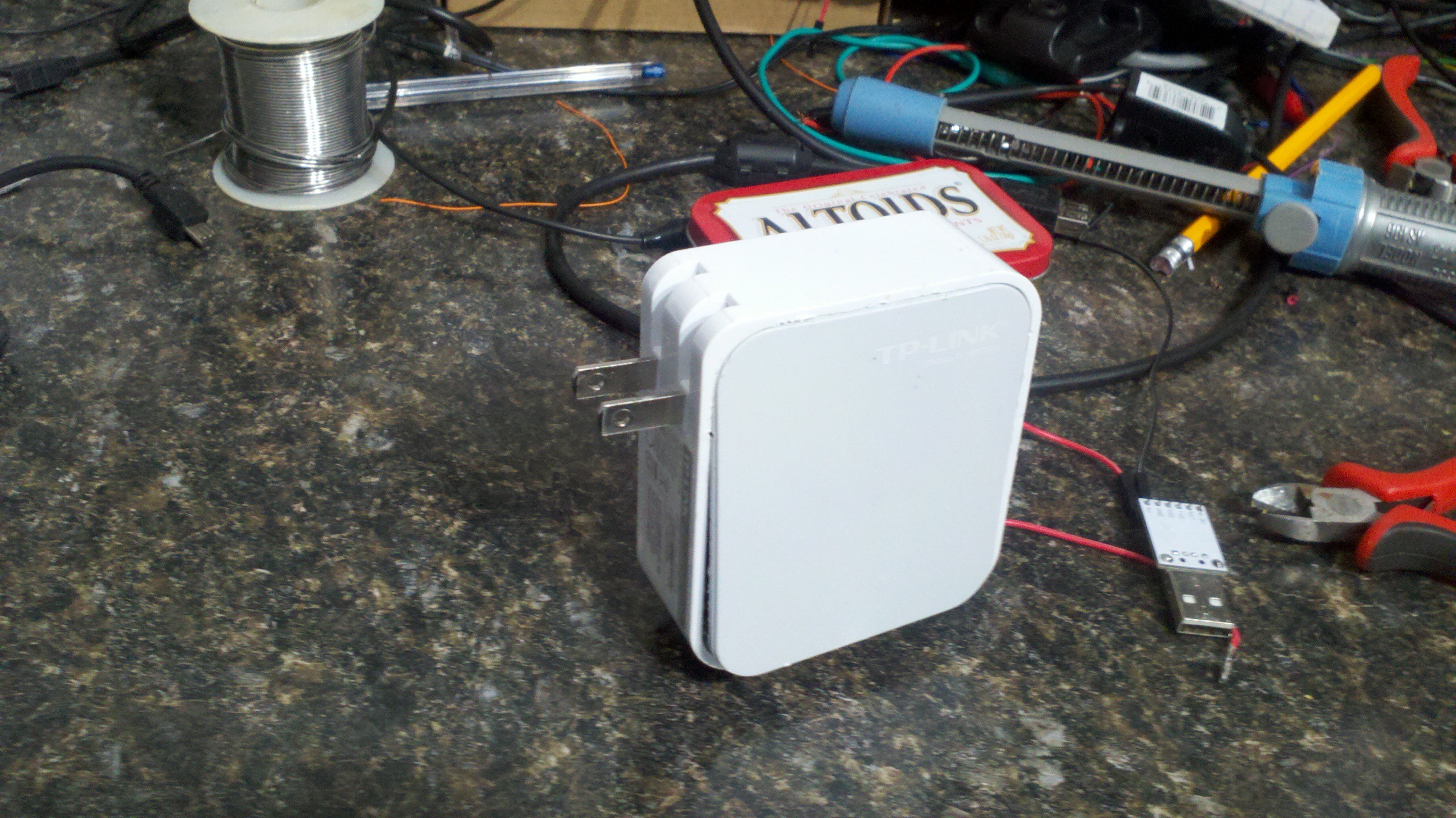
I had an old case from a defunt TP-link router that was just calling out for a project. I had been playing with the esp8266 and controlling a couple of LED's . Switch one of the LED's out for a relay and came up with a nice little project to control a lamp from wifi. While this project is specific to 2 wire lamp control it could be extended to a 3 wire device with minimal change.

A couple of warning notes. Cant stress this enough. You will be working with 110v AC that can kill you. Make sure you know what your doing. Make sure you relay is at least 15 amps. While I didnt include it in my project due to space issues You should install a fuse someone along the 110v path.

  • 1 × esp8266-01 This project used an esp8266-01 but any of the ESP8266 modules with GPIO ports will work
  • 1 × Relay board. You can build your own module or get one on ebay. Note: your going to be switching 110v so makr sure your relay will handle your current requirements.
  • 1 × 110v to 5v DC converter. There are some nice msall modules or you can salvage a wall wart for your power needs.
  • 1 × 5v to 3.3v power converter. The esp8266 is a 3.3v device and will be damaged with 5v. Since I couldnt find a 100v to 3v convert I went from 5v to 3v. There are a number different converters available. find one that meets your case space requriements.
  • 1 × misc wire and connectors for both low and high voltage.

View all 6 components

  • Amazon Alexa support with WEMO emulation

    Gary02/05/2017 at 20:59 0 comments

    Found that my project can be converted into a wemo emulator with nothing more than code changes. This allows amazon alexa (I think google device as well) to control the outlet.

    The code is not mine but can be found on github. The only change you need to make is work with my design is

    Change

    const int relayPin = D1;

    to

    const int relayPin = 2; (may vary if you didnt use the esp-01

    and set your devlice name to whatever you want.

    The codes comes with

    device_name = "box";

    I changed mine to

    device_name = "lamp";

    Code can be found at

    https://github.com/kakopappa/arduino-esp8266-alexa-wemo-switch/blob/master/sinric.ino

    Once you update the code, go to your alexa amazon account and go to smart home. Scan for the device. It should be found with the name you defined in device_name. After that Just say Alexa lamp on or alexa lamp off to control the device.

  • 2 month report

    Gary02/07/2016 at 19:43 0 comments

    I have had this up and running for a couple of months without issue. I have built 1 additional unit to allow me to turn lights on/off at a remote building. Working great.

  • Project complete

    Gary11/22/2015 at 16:19 0 comments

    The project has been completed and all instructions/code are include.

View all 3 project logs

  • 1
    Step 1

    WARNING................................WARNING.................................WARNING...............................WARNING

    WARNING................................WARNING.................................WARNING...............................WARNING

    This project uses 110v mains power and can be dangerous or deadly... Make sure you know what your doing. If your not comfortable with working with 110v AC dont do this project. Make sure when you testing you insulate 110v connectins and keep your hands away from any exposed wires.

    WARNING................................WARNING.................................WARNING...............................WARNING

    WARNING................................WARNING.................................WARNING...............................WARNING

  • 2
    Step 2

    NOTICE:

    THE ESP 8266 is a 3.3v device. DONT connect VCC or any of the pins to a 5v source or it will damage the device

    NOTICE

  • 3
    Step 3

    The first step is to find a case to house the parts in. I had an old TP-link router case that I used. It already had a two prong spring out 110v connections but any box will work. When planning your boxes figure out how your going to get the AC in and out of the box. A stop at your local bigbox hardware store should give you lots of idea. At a minimum a deepwall outlet/switch box will work but use your imagination. My project only uses 2 wire as thats what the case supported but if your planning on switching anything other than simple lights use a 3 wire system and include the ground.

    If your not sure about what wires goes where take a look online on how you would add a simple manual switch to a circuit and just replace the switch with your device.

View all 14 instructions

Enjoy this project?

Share

Discussions

Similar Projects

Does this project spark your interest?

Become a member to follow this project and never miss any updates