 Jose Ignacio Romero
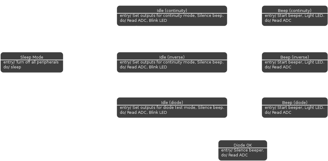
This is the basic state diagram for the continuity tester firmware. I opted to design it using a state machine since there are clear discrete states and transitions for each condition and mode the device can be in. Basically, there are 3 main groups of states, sleep, idle and beep, only the conditions that trigger the transitions change. The diode test mode has an additional "Diode OK" state which silences the beep after a quarter second if the voltage is within a diode drop.
Discussions
Become a Hackaday.io Member
Create an account to leave a comment. Already have an account? Log In.