 facelessloser
Layout
I’ve always tried to make my own tools and test gear to make my life easier. I started brain storming to see what I wanted to add to my own version of the backpack.
- It had to have a ISP header for programming
- FTDI would be handy to have
- Try and see if we can fit the crystal and caps on there too
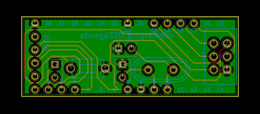
I started laying out the schematics in Kicad, At this point I didn’t know if I would be able to fit everything in the tight space I had. I realised that I didn’t have much space coming out from the sides of the chip, mainly because that would then start eating into my breadboarding area. But that didn’t stop me expanding out the ends of my chip where it didn’t matter as much about space.
Hardware
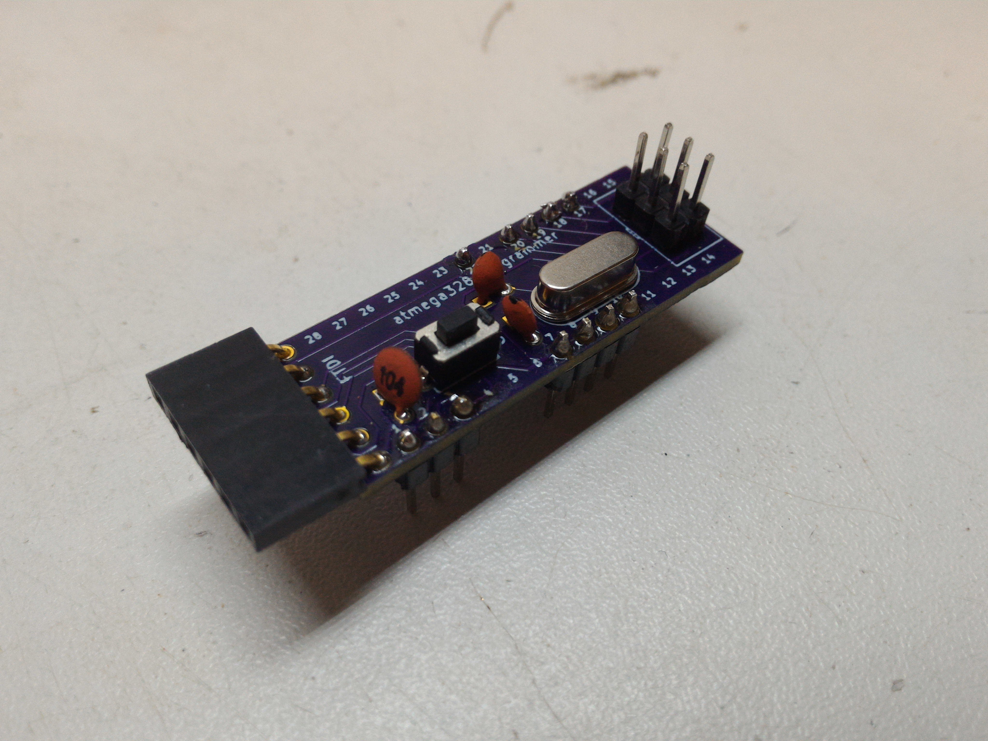
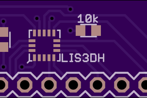
After wrestling with the layout I managed to fit all the things I wanted on the board.
- ISP headers
- FTDI headers (0.1uf capacitor)
- 16MHz crystal and 22uf capacitor
- Reset button
- ISP headers I just using 3 x 2 2.54mm pitch male headers, This saves space on the board (quite important in this case) and also means you don’t have to buy the over priced IDC sockets.
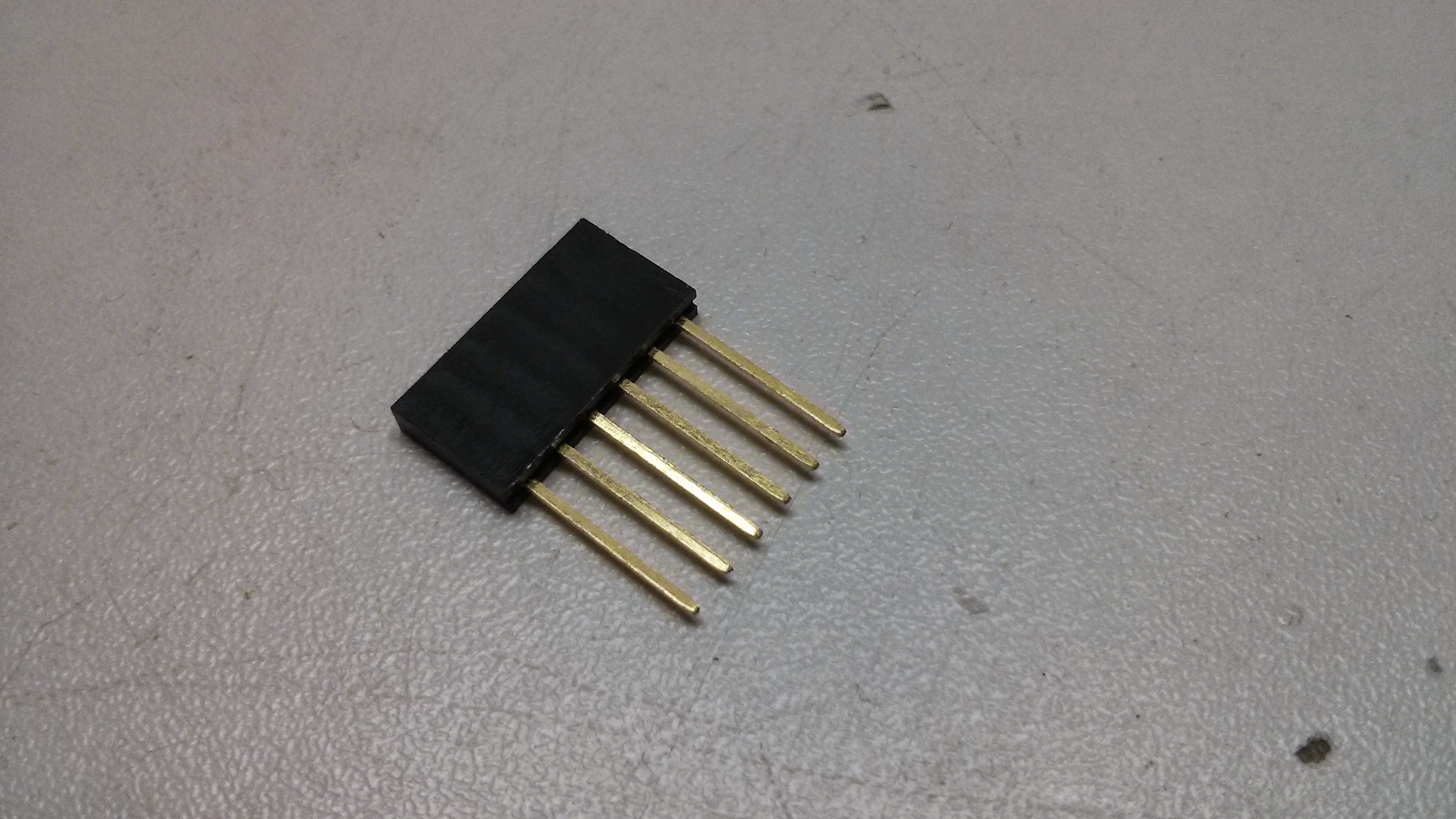
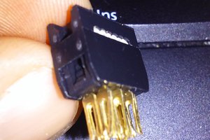
- FTDI headers I use a 6 pin female header with extra long legs so it can be bent over at the 90 degree angle for easy connecting with my current FTDI board. I also added a 0.1uf capacitor on the reset line to smother that out.
- The button connects the reset and ground lines together when pressed which causes the atmega328 to reset
- I also wanted to move the 16MHz crystal and 22uf capacitor so they would be out of the way
I added silk screen numbers for all the pins so it makes it easier to hook up the jumpers to the right pins
Before and after
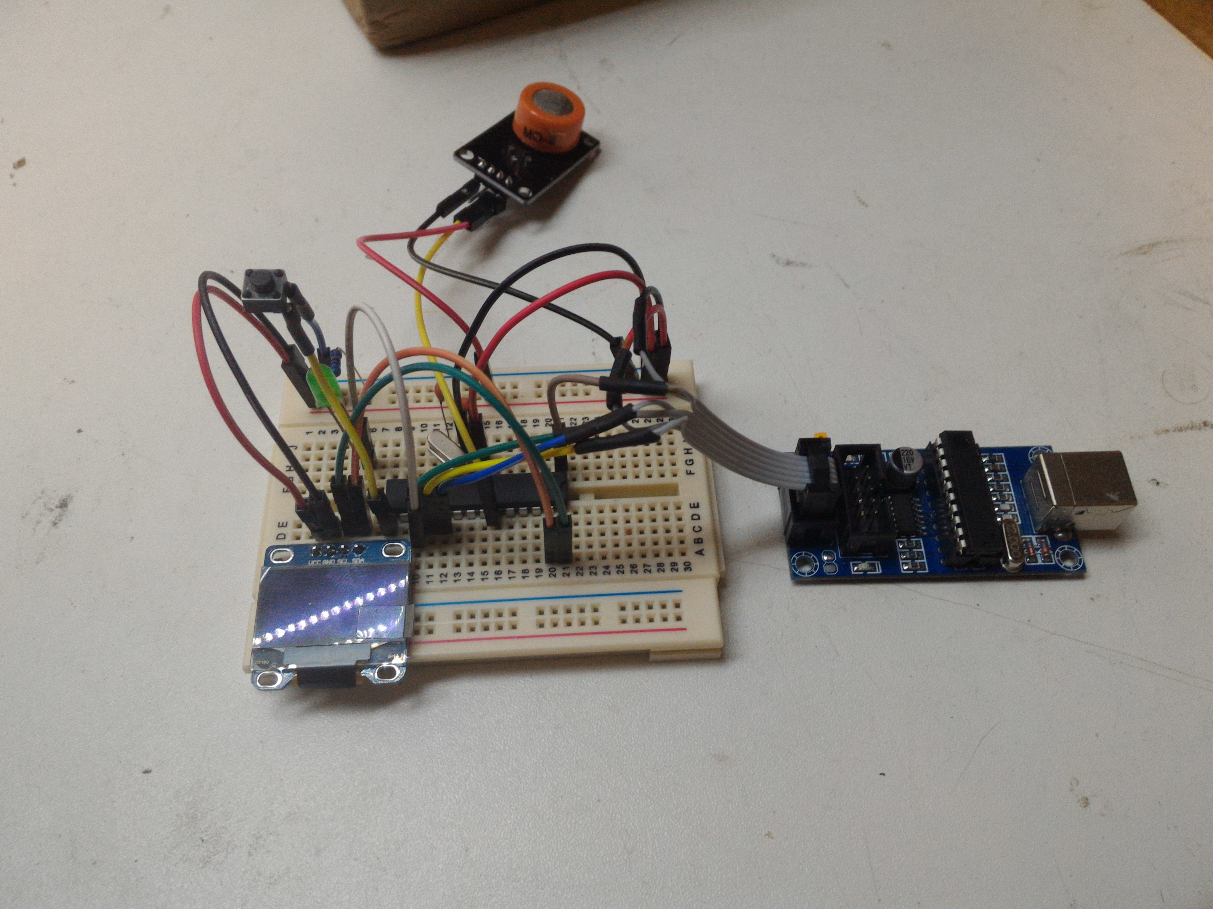
Before – As you can see there are jumper wires everywhere
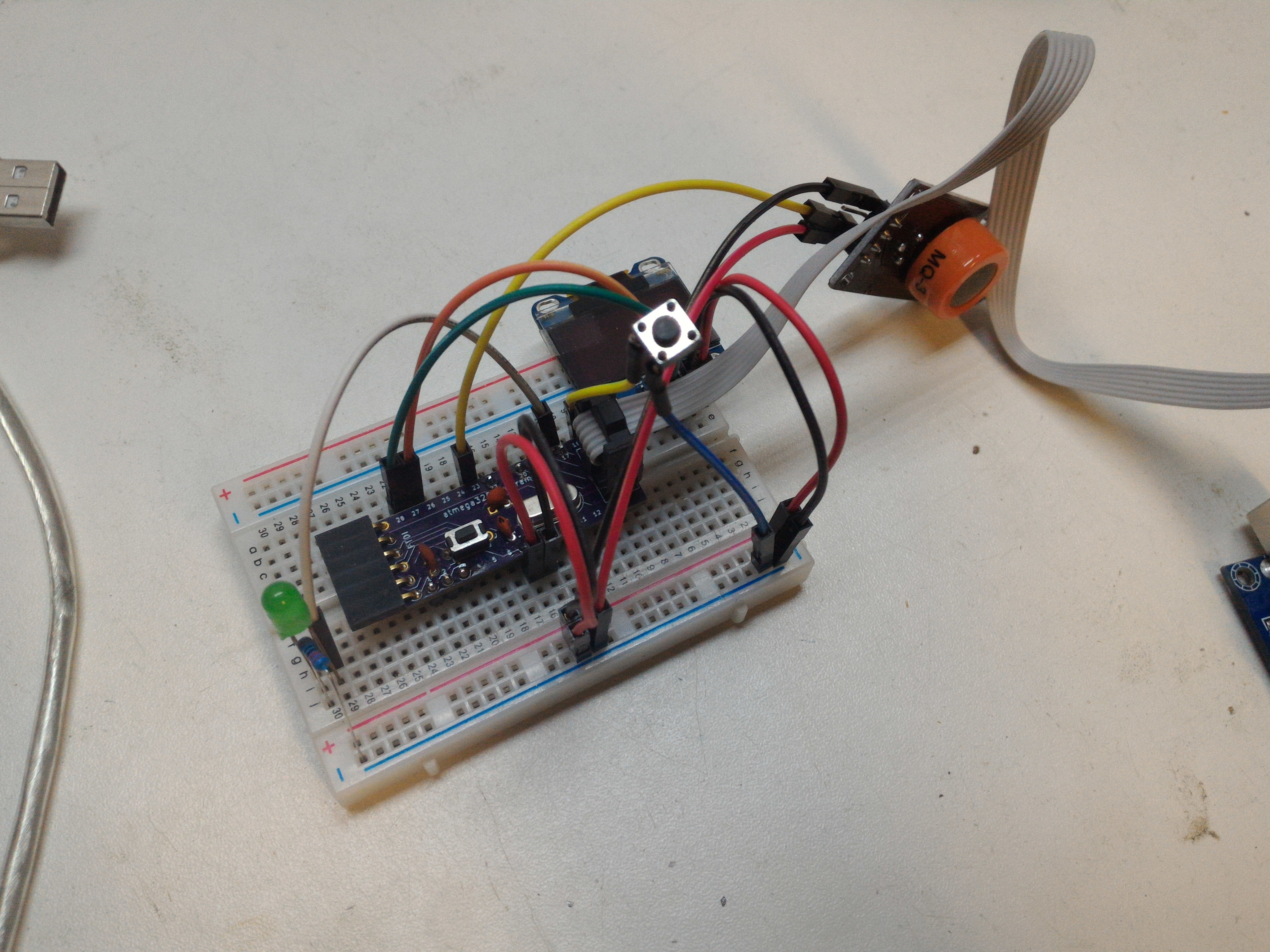
After – It looks a lot cleaner and you can clearly see the jumpers and where there connected to.
Video
Protip’s
- If you need to add a ISP socket to your project, Instead of using A IDC socket all you need is a 6 x 2 male header
Mistakes
I only really had one mistake with the PCB. For what ever reason I made 2 of the pins half a mm smaller than the rest, Wasn’t too bad but had to force the pins thought the hole. Make sure you double-check your board before sending it off to the FAB kids.
Files and links
- Gerber files are on my Github
- Hackaday.io post Here
 Christoph
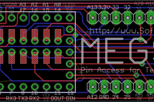
 T. B. Trzepacz
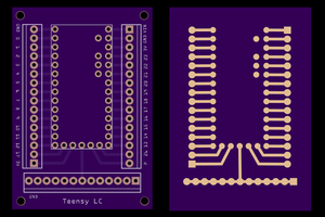
 Pete Prodoehl