 andyhull
TP4221 Based "Powerbank" mods.
Note: We are dealing with unprotected 18650 LiPo cells here. If you don't understand the risks of playing with unprotected 18650 cells, go away and read up about them before proceeding. You can also read my previous project on this topic.
TP4221A/B/C based "Power Bank" chargers litter the internet, and are generally of relatively poor construction, however on the flip side, they are cheap. Cheaper in fact than buying cell holders and a USB charger module. Therefore they make an almost ideal hackable 18650 LiPo (3.8V nominal) source. I say almost... they suffer from a few failings.
Note that not all "Powerbank" chargers are based on the TP4221, those that are, however all share the design below, with a few variations (single or double USB output, greater output capacity, 2, 3, 4 or more 18650 cells and so forth. They typically have only one button and a 3,4 or 5 LED "user interface". They may, or may not have the "Torch" facility.
A). The datasheet for the TP4221A/B/C is in Chinese ( http://www.datasheetbay.com/PDF/download.php?id=914396 ) Translated (badly) ( https://translate.google.com/translate?hl=en&sl=zh-CN&u=http://datasheet.d4usemicon.netdna-cdn.com/pdf/914396/TP4221B.pdf&prev=search ). I have yet to find an English language version. Google translate will help you out, if you need more details.
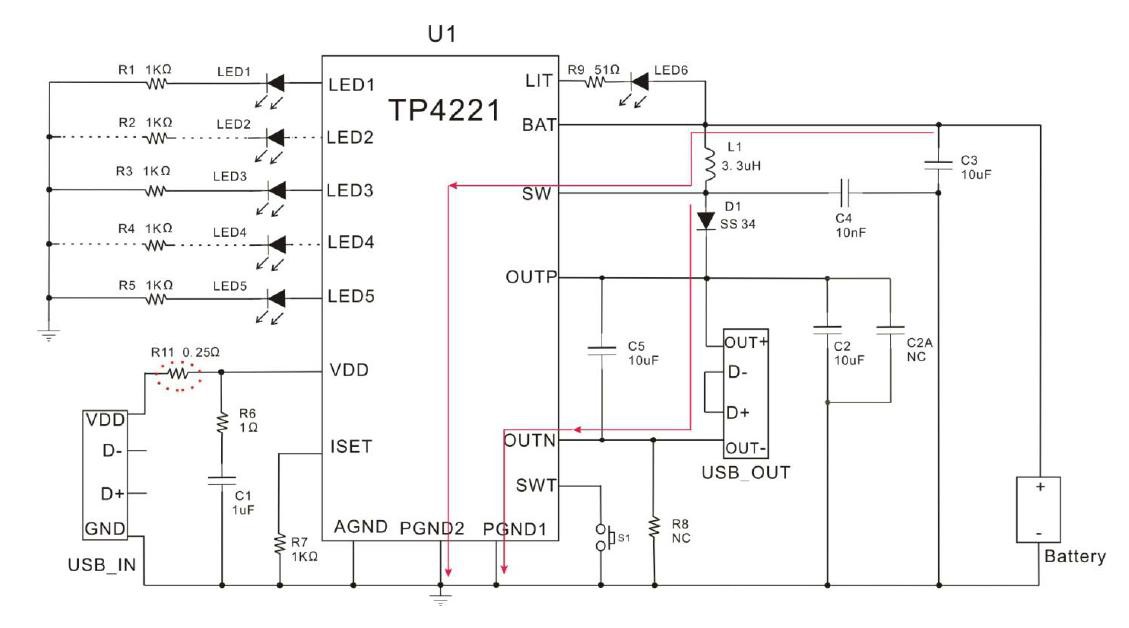
However since the schematic is written a language we can all understand, I've included it here.
Notice the LIT output. This is, according to the datasheet a 100mA NMOS Fet acting as a low side switch, intended to be used as a torch with a 100mA max LED (as shown in the diagram). It is switched on by two short presses of the status button (S1 in the diagram). This means that we can wire up the SWT input, and send it a couple of 500ms low pulses, separated by a 500ms high and the controller will switch on the LIT output.... so... whip off the LED, fire on a 2 pin header and you now have a switch-able 100mA 3.6v nominal feed from our Lipo.
This is perfect for low power microcontrollers, and has the advantage that if the battery gets low the TP4221 will shut it down for us.
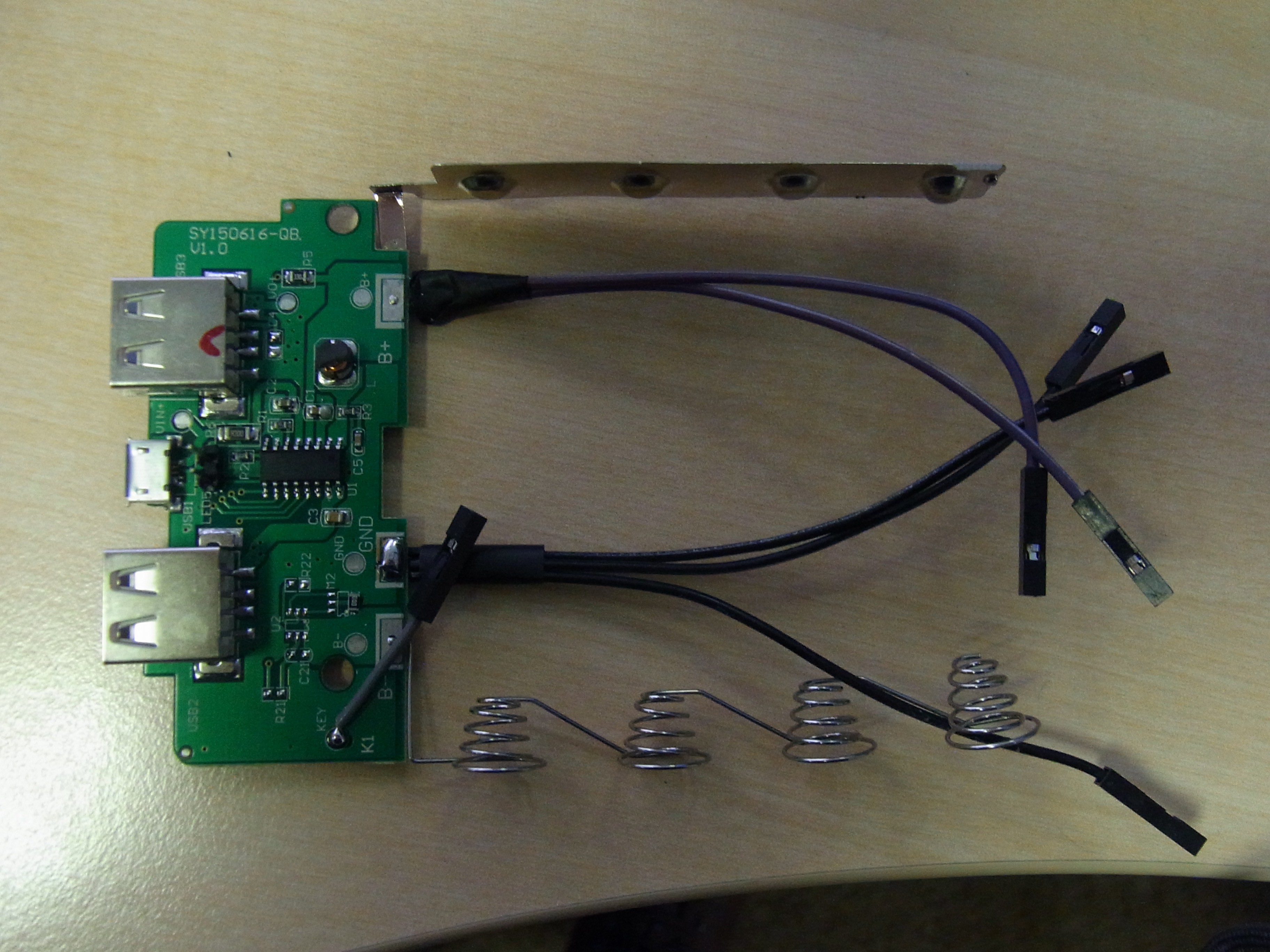
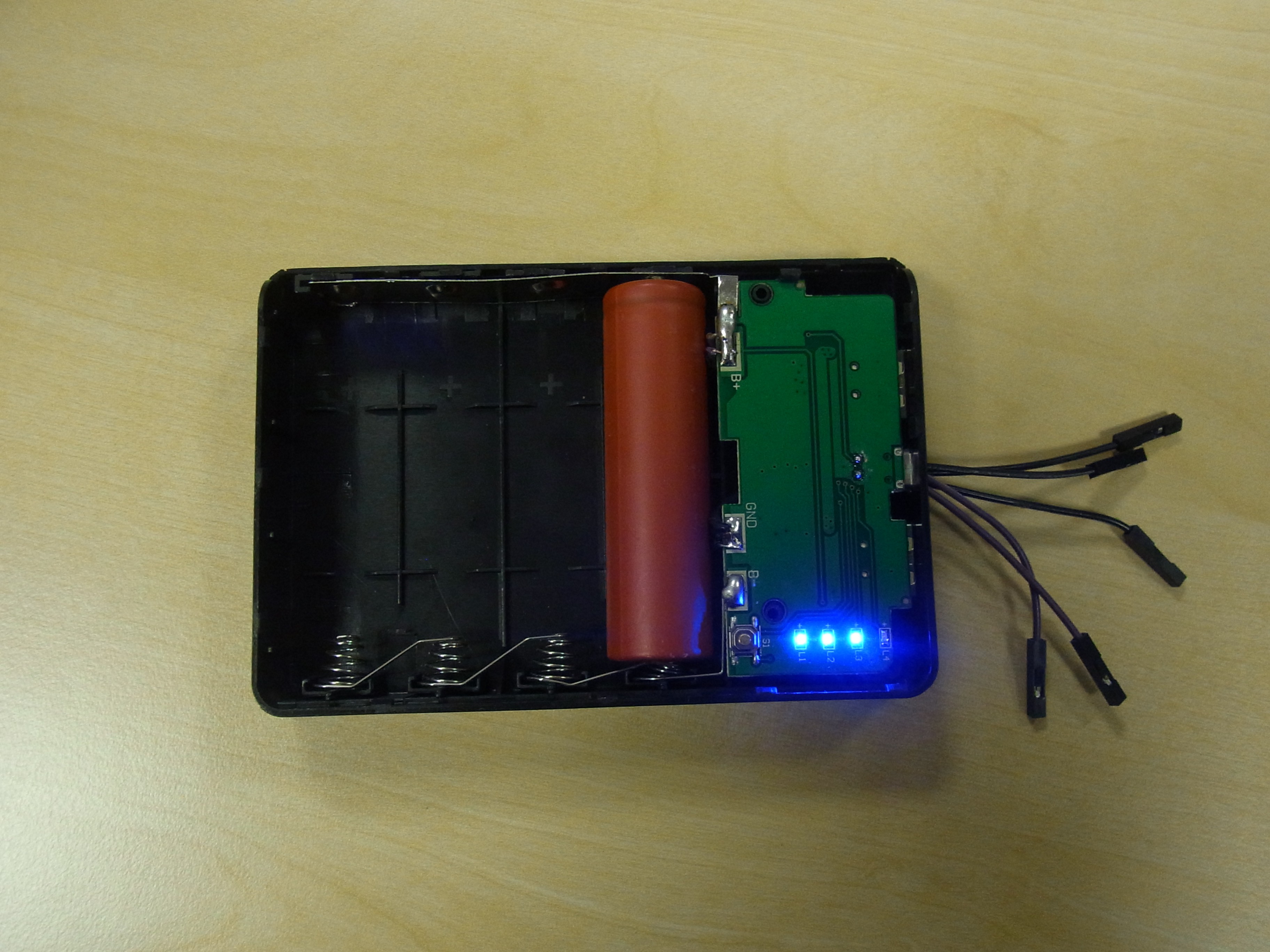
The picture above shows the board modified with header pins replacing the LED and the button (K1) wired to a socket. Additional wires are brought out of the front from the Lipo. Note that there is no over current protection, except for that tiny little 000 Ohm link between the B- and Gnd pads.
This is not ideal, I would suggest removing the zero ohm link and substituting a 2A micro fuse. However... I'm willing to live on the edge here, my metric calibrated eye suggests that little link will pop before the LiPos do. This brings me on to the next failing of these little power banks.
B) There is no protected 3.8V nominal output directly available, this is not a worry if you intend to use the 5V output, but if you want maximum efficiency, and therefore want to run directly from the cells, you will need to ensure your micro-controller, or whatever you intend to power shuts itself down when the supply drops to a point where it may damage the cells.
I will be using a Canon Powershot camera and CHDK with a dummy battery in the camera. Since the Canon camera shuts itself down when the battery voltage gets low (<3.2V typically), I wont worry too much about this. I would advise checking the cell voltage before each charging session, just in case it has dropped to a dangerous level (<2.8V), or any of the cells have failed.
Now for the third gocha.
C) The 5V USB outputs will shut down (or fail to start) if the load on them is <50mA, at least that is what the datasheet appears to say... I haven't verified this.
... and finally in my criticism of this otherwise useful little device.
D) The build quality of some of these "Power Banks" is dreadful. I guess for $2.45, what do you expect, gold plating?
Here is the ebay listing for the devices I purchased.
One of the ones I just got delivered didn't even have the +Ve battery tab soldered to the board, it was connected to a blob of solder and some fresh air. Another one appeared fine, but the spring contacts parted company with the board when I removed it from the case to do some surgery.
E) With only one LiPo fitted, the cell gets rather hot when charging, this is presumably because the charge current assumes four cells. It doesn't actually explode or catch fire (at least not in the limited testing I performed), but I would suggest using four cells to keep the temperature down. There is no provision for a thermistor in the schematic above, so err on the side of caution. Thermal runaway with LiPos is spectacular and dangerous.. magic smoke in large life threatening quantities, accompanied by actual flames and toxic fumes.
Did I mention... expect QA on these "PowerBanks" to be non-existent.
Since I will be leaving these things out in the wilderness to take pictures, the build quality is not an issue. I figure if they fail, I'll get a few more. The chances are the cold and damp will cause them to fail fairly quickly anyway.
Recycled 18650 cells (free) + ebay £4.00 or less canon cameras + cheap ($2.45 or thereabouts) "Power banks" = almost disposable wilderness cameras. The SD card in the camera is worth more than the rest of the build put together.
So how do I hack it?... proceed as follows..
1) check that all of your LoPos are within a few mV of each other, and charged to >3.0V, for preference, fully charge them separately before fitting them for the first time.
2) Solder a couple of wires to GND and B+ respecitvely. Add any additional mods you feel necessary based on what I have said above.
3) Cut a suitable slot in the crappy plastic to lead these outside the housing, or if you have removed the LED, feed your wires out of the hole that it previously occupied.
4) Examine and fix the "PowerBank" solder joints.
5) Fit the batteries.
6) Charge them up in the "PowerBank" with a USB lead, while keeping a careful eye out for magic smoke (certainly do this the first time you charge any recovered LiPo cells).
7) Re-assemble and attach to your project.
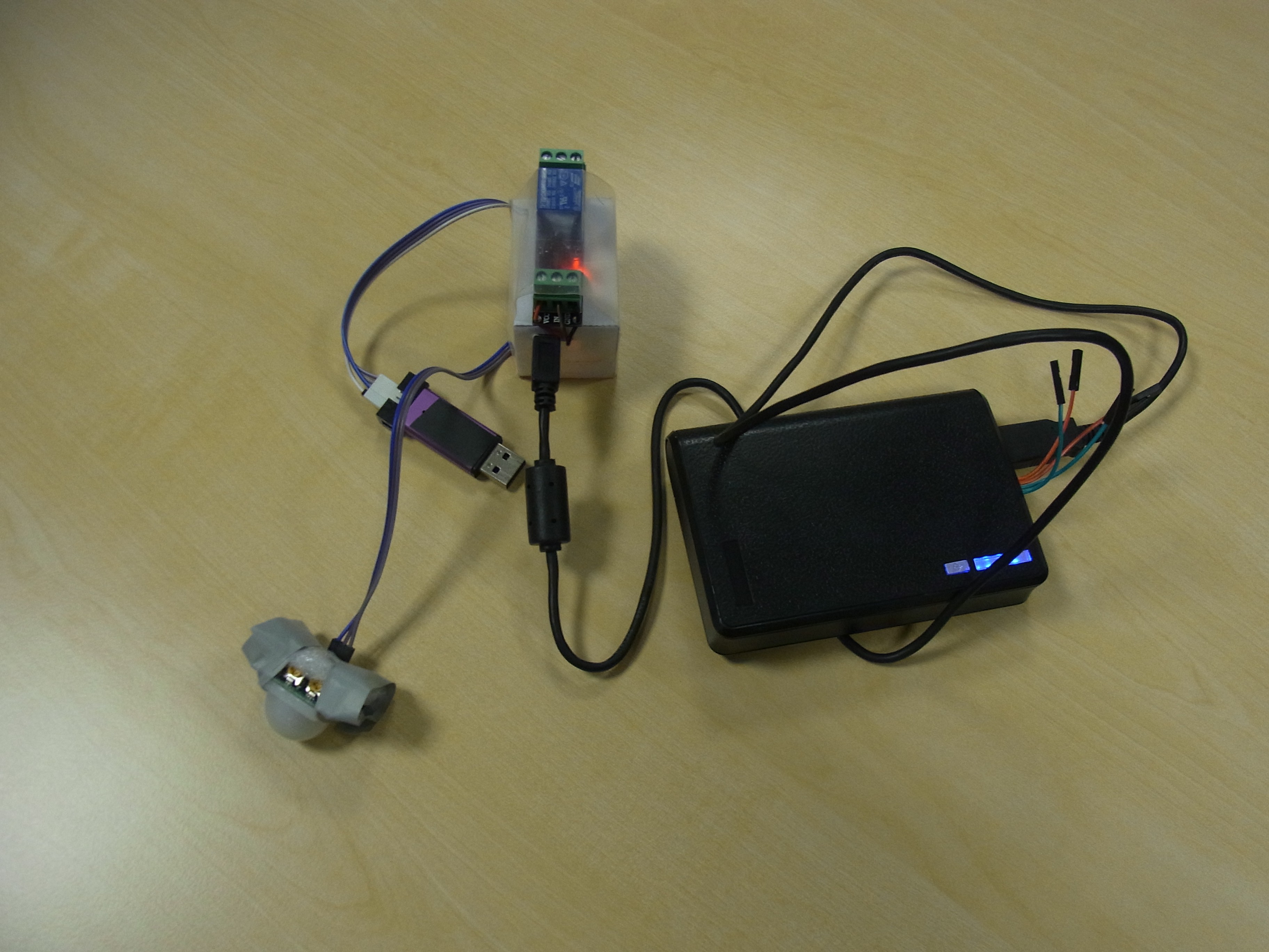
8) Use your modified "PowerBank" to take pictures, trigger a PIR alarm, power an ESP8266 portable wireless node, or whatever else you can think of.
Finally if you want a good read on the subject of low power, you should check out Jack Gansell's "Hardware and Firmware Issues in Using Ultra-Low Power MCUs"