 engunneer
My second order of boards was for the Arduino Host Adapter and the Breadboard adapter.
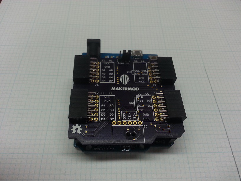
The Arduino shield ended up having a few minor problems. The SMD pins on the bottom had pads that were too small and actually faced the wrong way, too. I did some creative soldering and got it to work.
I also had a few swapped labels on my pins. This was my first shot at documenting the port designations in the silk. I'm trying to keep all components on the bottom, except for the connectors.
The last thing I wasn't really happy with was the 3.3V/5V jumper for VCC select. I think I want all future Hosts to be 3.3V only, and 5V controllers will need level conversion. This is tough, because it moves cost from the modules to the host for 5V hosts. This will also be a problem on Analog breakouts. Still not sure exactly what I want to do here.
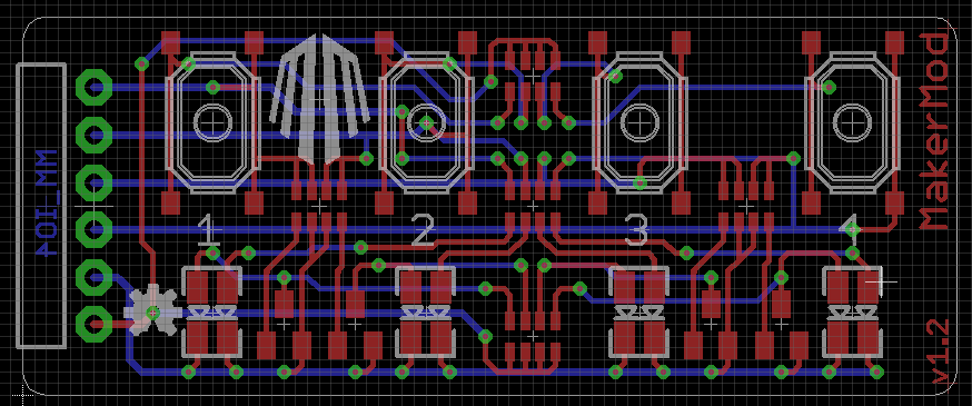
I also got to test the I/O board from the last post. It definitely didn't work the way I expected, and I also had a few footprint issues, so I have a new version drawn up that will be in the next PCB order. I'm pretty happy with the layout. I am finicky about how I want to run my traces, and this layout appeals to me. I may decide there must be a via in the OSHW logo from now on.
One of the goals of the project is to still allow fast prototyping using breadboards and the soldered proto modules, so I designed an adapter for my solderless breadboard to make it into a large MakerMod module.
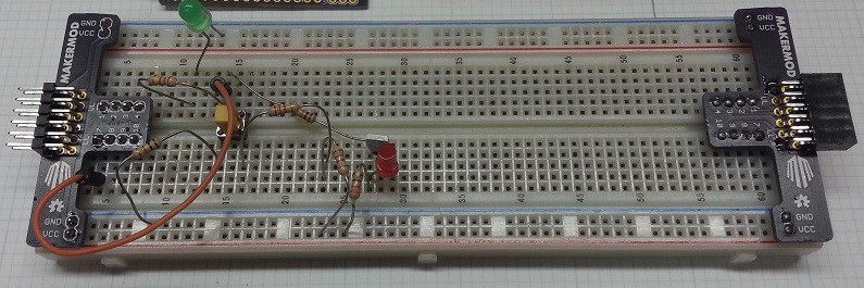
The neat thing here is that both ends actually use the same PCB. Flip it one way to make a male port, and the other way for the female. VCC and GND are routed to the power rails on the side of the breadboard. The circuit shown here is actually a single channel of v1.2 of the Button and LED board, with some series resistors making the values I wanted.
Discussions
Become a Hackaday.io Member
Create an account to leave a comment. Already have an account? Log In.