Motivation
Our existing boat, now named TSV Disputed Right of Way, is a great platform for software, electronics, and sensor development. However, for long ocean crossings, sail is where it's at. My off the cuff explanation for this at MakerFaire is that the wind blows more often than the sun shines. This is generally true at sea, and it's even more true in the waters we need to traverse in order to circumnavigate the globe.
However, sails on an autonomous boat, especially one intended to be at sea for long periods, are demonstrably tricky. The Microtransat Challenge, an autonomous transatlantic race held every year since 2010, has yet to crown a single winner. Last year, none of the competitors even made it to the starting lines. The farthest any boat has covered was 653 km, most of that under shore command. The farthest any boat in the race had covered autonomously as of 2014 was 408 km. The World Robotic Sailing Championships are marked by numerous failures to finish among the competitors. The current record holder for autonomous sailing is the Saildrone folks, who have made it from San Francisco to Hawaii.
We're doing something a little different than most of the robotic sailboats we've found, and that's using a self-tending wingsail, similar to Saildrone. It's a rigid wing, mounted vertically in the boat, and free to rotate. Attached to the trailing edge is a boom with a movable tail that controls the angle of attack of the wing. This allows the control system to set the direction and magnitude of the propulsive force provided by the wing. This only requires a single, small actuator placed well clear of the water. If configured correctly, the actuator can be self-locking, meaning that it does not need power except when moving. The result is, at least conceptually, more durable and requires less electrical power than other options. We're doing Saildrone one better by using multiple sails (two or four) to eliminate the need for a rudder, which is another potential failure point.
Hull Design & Construction
Over the past few weeks, I built the hull and sails for our first cut at building a test boat for this concept. The hull is deliberately the absolutely simplest way to make a hull I know of -- an Advanced Sharpie/Bolger Box made from laser cut plywood. This meant the boat's length was restricted to the width of the laser cutter at Metrix, 42 inches. This is more than long enough. The beam (width) is set such that I can use some 5" Beckson twist-out deck plates for hatches and still have room for a keel/daggerboard at the center of the boat. That came out to eight inches, and I set the hull depth equal to that. The shape of the boat is defined by two arcs struck along these lines, as you can see from the top of the boat:
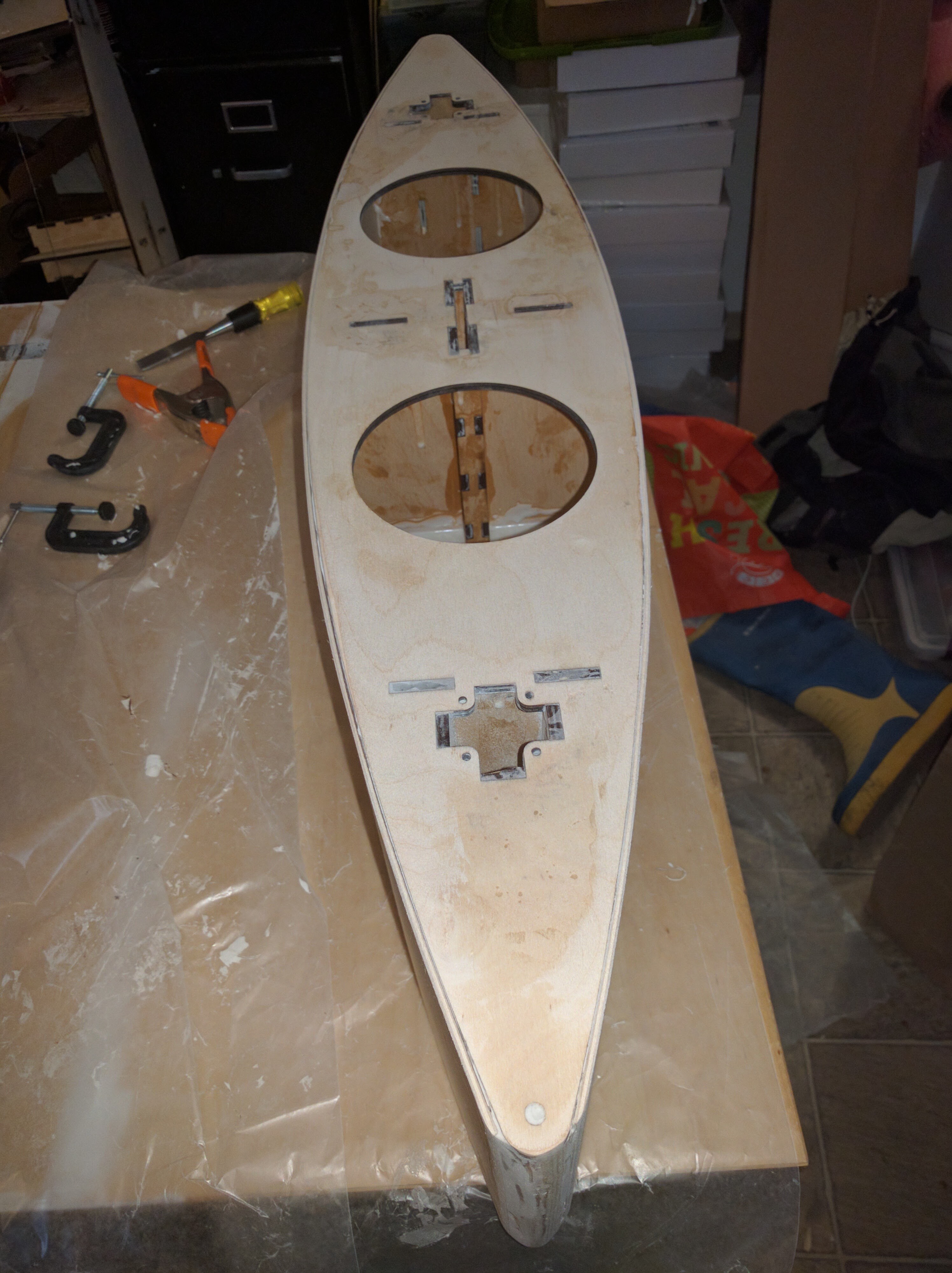
I cut the bottom, deck, bulkheads, sail trunks, and centerboard trunk from 6mm baltic birch and the sides from 3mm. The stem and stern posts are just a couple of pieces of 1.5" dowel. I glued the pieces together with thickened epoxy (TAP 1:1 epoxy and microballoons, because lazy) and I think it came out pretty nice for as easy and cheap it was to put together. This picture of the hull during assembly lays out the various internal pieces nicely:

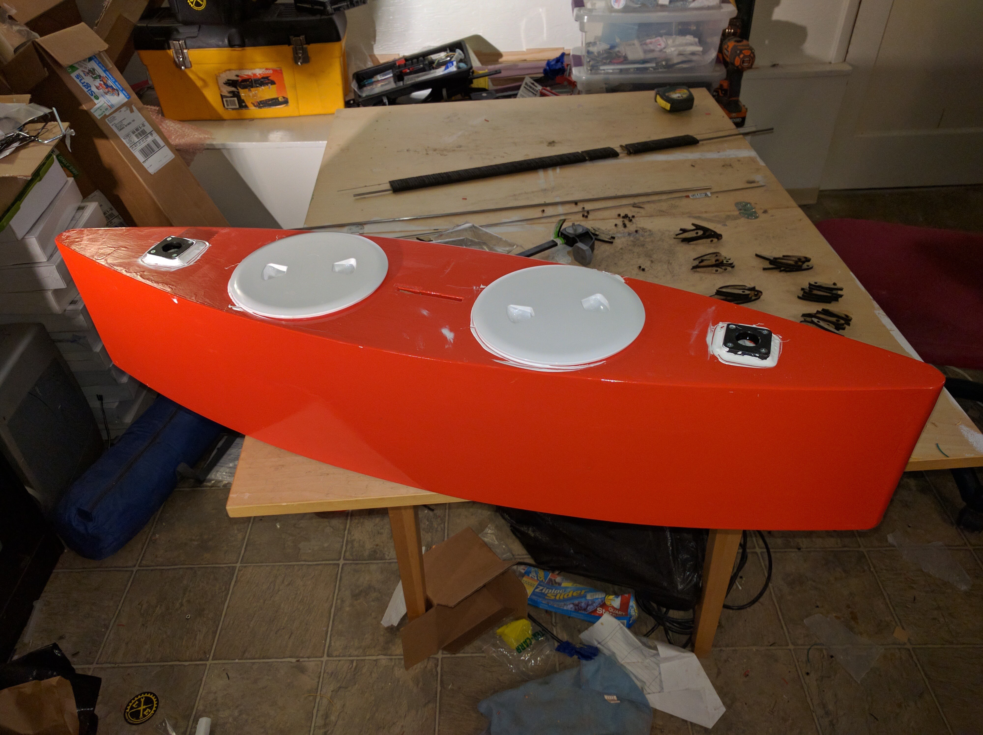
Naturally, I gave it a nice coat of paint for Makerfaire:
The sail bearings are double-sealed stainless skate bearings from McMaster held in the NEMA-17 sized bearing blocks from our friends at OpenBeam. In a failure of technological panhandling, I failed to get the bearing blocks for free, but they're cheap enough I don't care much. Using the skate bearings sets the size of the wing pivots to 8mm, which is a reasonably convenient size. 8mm stainless rod came from McMaster (again). This mounting arrangement is great because it gives me the ability to easily and quickly swap sails.
Wingsail Design & Construction
The design of the wingsails is pretty basic. I rooted through airfoiltools.com looking for the highest lift coefficient available in a symmetrical airfoil. It's not terribly well organized for that sort of search, so it was slow and I settled on the good old NACA 0021 as the best option at the relatively low Reynolds numbers (~70,000 @ 10 mph windspeed) we can expect for wings of this size. The 0021 means it's a symmetrical foil whose maximum thickness is 21% of the chord (distance from leading to trailing edge). The section looks like this:
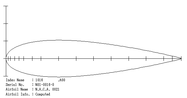
The tables also give me the coefficient of moment around the 25% chord point. This moment attempts to return the angle of attack to zero degrees. The tail on the wing sets the angle of attack by producing a moment that balances out this moment at the desired angle of attack. The relationships between lift, moment, and angle of attack are sufficiently smooth and monotonic that no further control is required. I calculated the size and location of the tail based on these numbers... and I'm not really sure how well I did. The experience from doing it this time should allow me to correct for next time. In particular, I suspect I will want a large tailplane closer to the wing, for packaging reasons if nothing else. It would also raise the Reynold's number of the tail, which would increase its effectiveness.
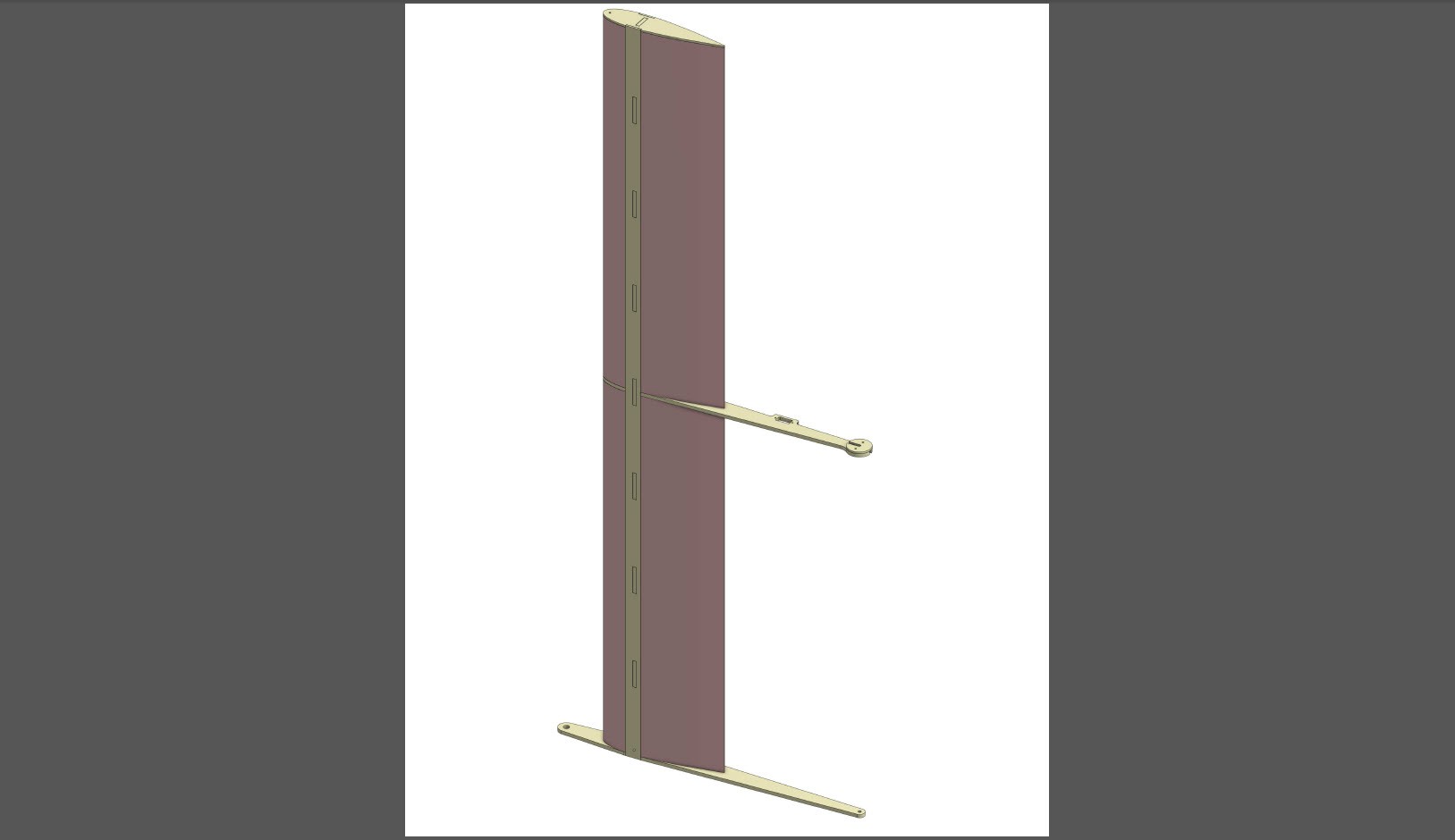
The wingsails have a laser cut wood frame, filled with hot wire cut pink foam and covered with Monokote, an adhesive-coated heat shrinkable film designed for covering model aircraft. The length of the wing is set by two things -- the maximum diagonal distance of the Metrix laser cutter and the sizes of pink foam available at Home Despot. The foam comes in 2' x 8' x 2" sheets, so the wing is just over four feet (two sheet widths) long... which just fits diagonally. Here's what my Onshape assembly looks like (light yellow is wood, pink is foam):
While cutting the foam for the wingsails, I learned that hot wire cutting is trickier than in looks on Youtube. Next time, I will use the hot wire cutter to make blanks that are then routed or sanded to shape. I wasn't able to get a very good wing shape, but it looks alright when covered with Monokote:
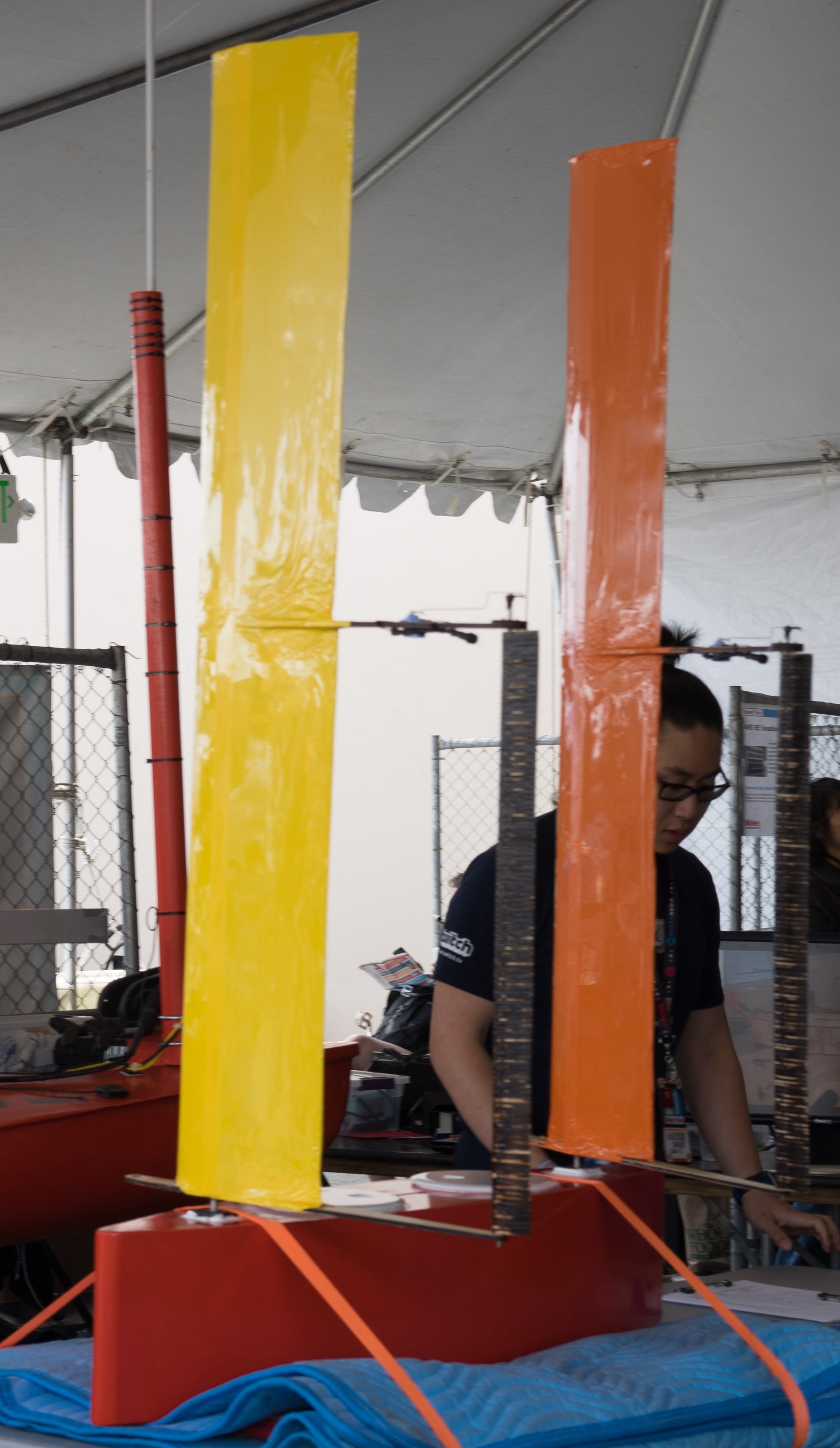
The wings are different color so I can tell which end is which from a long distance. The orange wing is the forward wing.
Figuring out how to make the tailplane turned into a bit of a trick. It's too small for wire cutting and too big to be 3D printed at a reasonable cost. I ended up laminating the tail planes out of 118 slices (each) of laser cut 6mm birch. This was possible because I ran two rods through the tailplane -- a 3/16" stainless rod to provide the main pivot and a piece of 0.039" music wire up the trailing edge. This is very easy to do with a laser cutter. The only difficult part was stacking them together and gluing them up.

See the wing design at OnShape.
Control & Electronics
The electronics are still mostly notional, but I'm hoping to get them assembled in time for Toorcamp next month.
Each tail is controlled by a micro servo mounted on the upper control arm and driven by an Arduino MKR1000. I installed the servos before Makerfaire, and lots of people (including me) wiggled them. I suspect this may have damaged them.. we will see.
I won an MKR1000 in the Hackster.io contest earlier this year and picked up a couple at MakerFaire. In order to avoid having to deal with rotating contacts or anything like that, each wing has its own MKR1000, and the third is the remote control. The forward (orange) wing is configured as an access point; the aft wing and the controller connect to it.
I'm looking at two possible control schemas. Both use a pair of knobs on the controller. The most obvious way is to attach each knob directly to one tail. This gives the most direct control, but strikes me as a bit unintuitive. The other is to dedicate one knob to tack/overall power and set the differential control with the other knob. I'll code both up and see which works best in context; I might even have a toggle on the remote to see which is which.
Discussions
Become a Hackaday.io Member
Create an account to leave a comment. Already have an account? Log In.