Amar Potdar
-
PCB | Routing
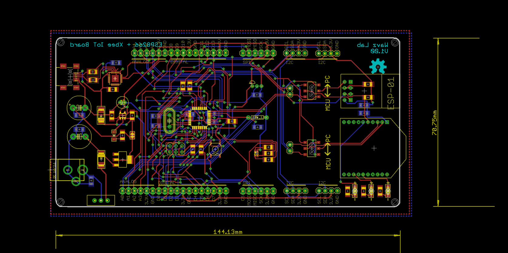
04/14/2016 at 04:29 • 0 commentsDone with Routing.
I guess, I have to call this project off.
Due to my insane decision to put analog and digital pins on both sides of the board, I messed up routing. And violated enormous numbers of design rules.
![]()
I wish you Hackers scrutinize this design and comment below. I need your suggestions and opinions on this.
-
PCB | Part - 1 | Placement
03/28/2016 at 10:34 • 0 commentsOK, Schematics isn't the tough part of your project, once you have working & tested circuits of each module. You see, schematics & routing ain't challenging for me but Placement, tht's really kill your brain's out.
You have to iterate several times even after you start routeing the board, to get best results. and don't neglect DFM.
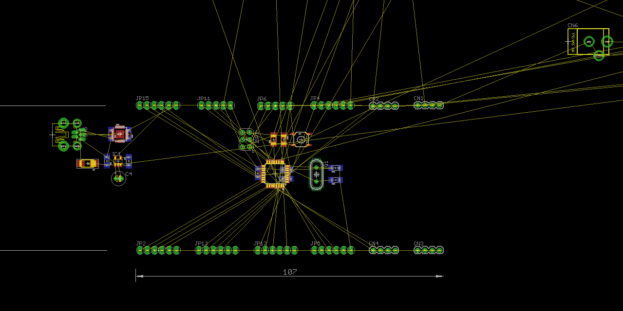
![]()
I was figuring out, what would be the best pin placement. I was looking for way such a that it would be flexible to access ANALOG & DIGITAL pins from both side of the platform.
I think this is my terrible idea, as you can see, air-wire flying all over the board, it is going to be challenging task to layout this board. Haaa! Auto-router might die routing this.
Also, I have to keep in mind the from-factor of below 10cm x 10cm in dimsens..
Bonus Story:
Thanks to my Internship at AMI tech. where I was involved in development of wireless Automatic Meter Reading systems. It's there I learn to play with Wireless modules-protocols like Zigbee, Sub-1 GHz.
-
Schematics | Part - 2
03/26/2016 at 14:52 • 0 commentsSchematics design is done. it wasn't tough or was it? Anyway. I have reviewed once. but still am little skeptical about it. Will need thorough review, before I head to PCB design.
As described in my last log, am taking absurd approach on GPIO. and I think it's going to be hard designing PCB, As ANALOG and DIGITAL pins are on both sides of the board. Let's See.
Schematics design using EAGLE V7.2.0
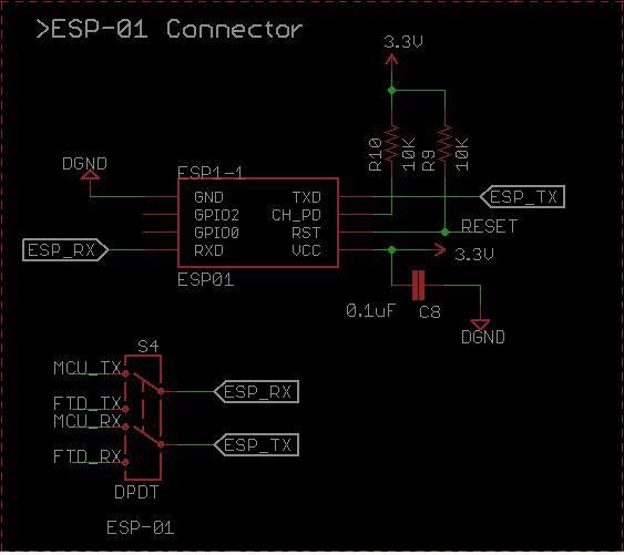
ESP-01 Connector:
DPDT Switch has been added for both w-less connectivity. This will allow to access w-less module either over MCU for application or over PC terminal for configuration.
![]()
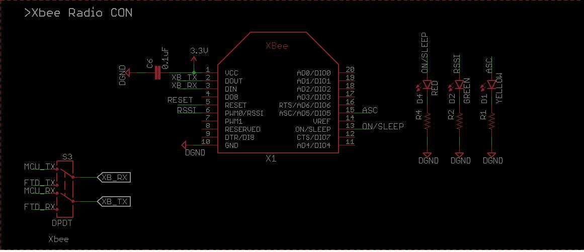
Xbee Connector:
![]()
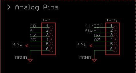
GPIO:
- ANALOG:
![]()
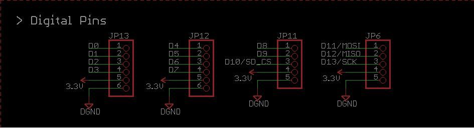
- DIGITAL:
![]()
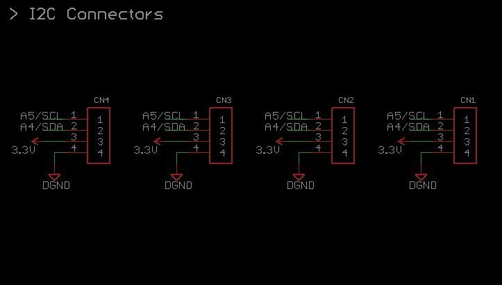
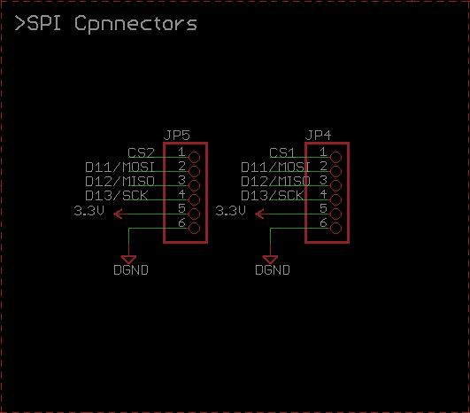
- I2C & SPI:
![]()
![]()
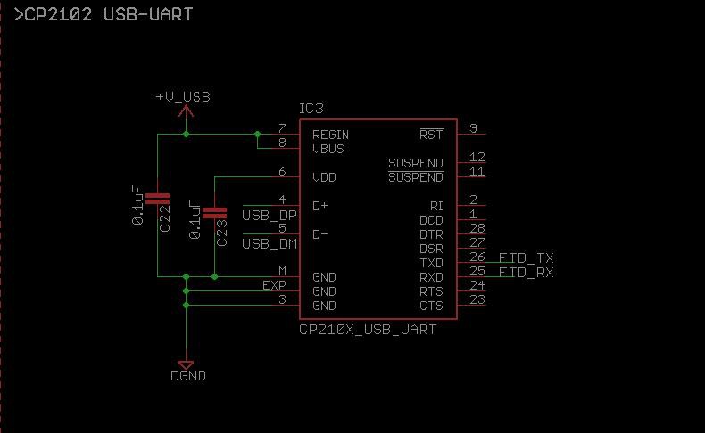
- USB-to-UART: CP2102
![]()
-
Schematics Design | Part - 1
12/08/2015 at 21:43 • 0 commentsAfter drafting the basic features and taking community feedback over Reddit. I decided to move ahead with proposed design. Thanks for suggesting cheap CP2102 for USB-UART.
- Atmega328P: +3.3V Power, 8MHz Clocked.
- Power Supply: USB & DC Jack for Powering the board.
- ESP-01 and Xbee Radio Connectors.
- Sensors: I wanted to add one Analog and one digital sensor on board
- GPIO/ Pinout: Analog-digital pins on both side of the board. Extra SPI & I2C pins.
Let's dive deep :
Power:
- LDOs
- LM1117: +5V/1A.
- SPX3819: +3.3V/500mA.
Sensors:
- DS18B20 [Digital]:
- Popular One-Wire Digital Temp-Humidity Sensor.
- LDR [Analog]:
- Low Cost, Simple & Easy to use Light Sensor. Just add fixed resistor to from volt. Divider and you are ready to go.
W-Less Connectivity:
- ESP-01:
- No doubt, It's the best, it's the cheapest, Couple of AT cmds, and you are connected to web.
- Xbee :
- OK, Xbee still is widely used radio modules around. At my university there are many students & researchers who use them daily.
GPIOs:
- Analog: 1x6 Pin Header = 2 nos.
- Digital: 1x5 Pin Header = 4 nos.
- SPI Pins: 1x6 Pin Header = 2 nos.
- I2C Pins: 1x4 Pin Header = 4 nos.
You might have few questions in your mind:
- Why Xbee radio sockets?
Ok, As stated earlier. Xbee family is available & used almost every where and plus they have been around for while, we are using them for past 4 years, works great. Although they are costly compared to others like- HopeRF, Dorji RF modules.
If you go through the Xbee series, one good thing is that all of them are pin compatible, works serially on AT cmds. that means, you just have to plug-&-play according to your application.
Click the link below to discover more about them.
- Why GPIOs are like that?
Well, I know Arduino-like pinouts are best. but still they are little cumbersome to access while you are hooking some sensors & actuators.
So, I decided to go with this insane idea to put Analog & Digital pins on both side of the platform. Plus, I also added extra SPI & I2C pins, they might come handy.
I have also added +3.3V and GND pin on each connector, listed above.
Arduino Enabled : (ESP8266) WiFi & Xbee IoT Board
IoT Rapid prototyping platform : Atmega328P at heart | ESP-01 + Xbee radio | Sensors - DS18B20 + LDR | Enough GPIOs