 Patrick Van Oosterwijck
The rev 1 layout is done! It will be highly disappointing to many people. Not only was it not designed to wear around your neck (although I'm sure enterprising hackers could make that work), but it does not contain ten million LEDs either! In fact, there aren't any LEDs on it at all!
I don't know what I was thinking when I created this abomination. How am I expecting to get any attention at all for this project without covering it with LEDs? Insane. Here I am thinking about mundane and boring concerns like power conversion efficiency, EMI, snubbers, transmission line differential impedance, ground plane preservation and manufacturability, while I completely forgot about the first and foremost raison d'être for any electronic project: flashing LEDs.
I pretty much submitted it to the Hackaday Prize for nothing since no judge will ever bother to look at it. Especially not since I will likely not bother to make a flashy video either to explain why this thing is cool even without any flashing LEDs. I must be insane if I expect people to read instead.
Well, at least I came up with a pretty slick logo that may help grab some eyeballs, so all may not be lost:
Yes, I do know how to spell "wasp", but I am a native Dutch speaker so I couldn't help myself. And you have to admit that it looks kinda badass. :)
Final version should probably have a black background with yellow silkscreen, but OSHPark PCB renderings look really nice for showing the finished look of a board, so we'll go with a white/purple wasp for now. Here's the component side:
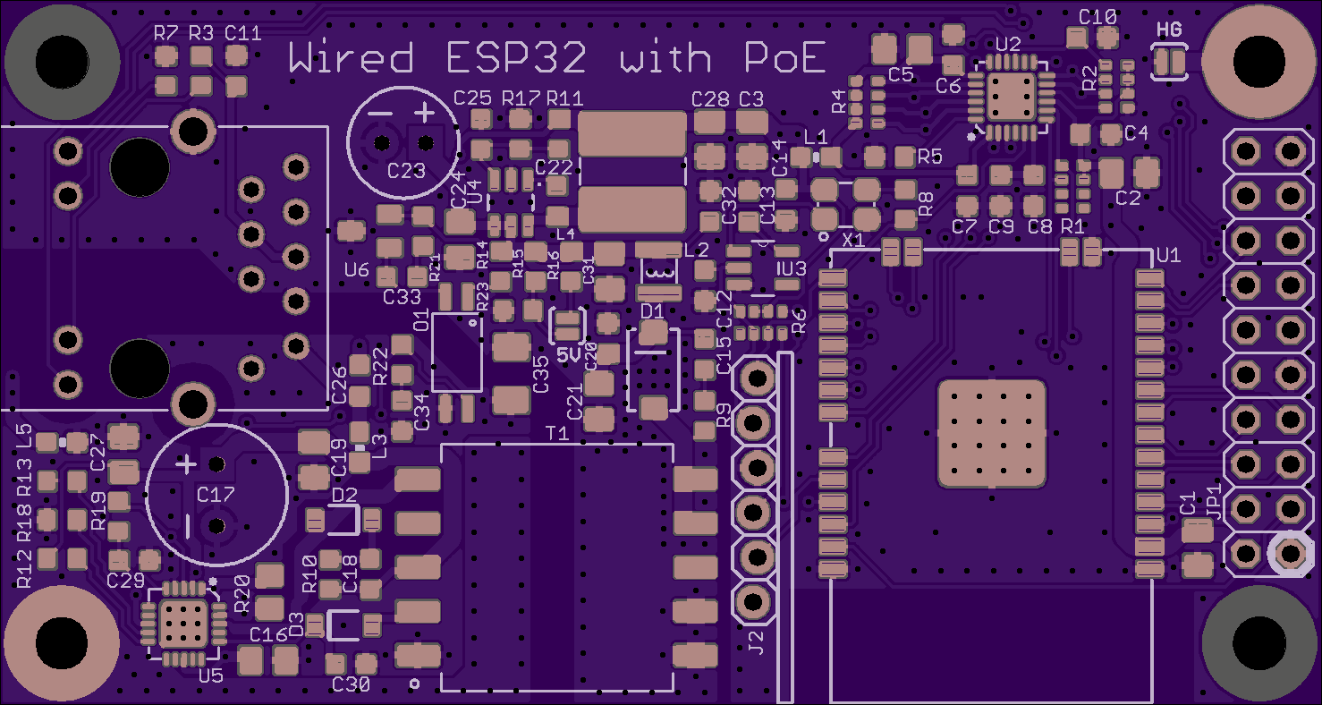
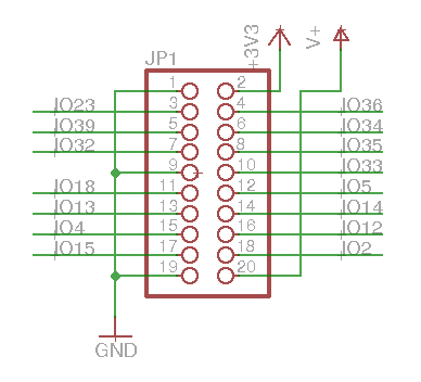
I managed to cram it all into 75 x 40 mm. The header in the middle is where the ESP32-Prog sub module can be installed for programming and/or USB serial terminal. I also added a solder jumper to allow you to select 5V power output instead of 12V. I'll have to wait until I can do testing to see how well this will work. The flyback transformer turns ratio is optimized for 12V output, but even if I can't get to the full 13W output power when the 5V option is selected, it likely still is a very useful feature to have. The header on the right side is where you connect your application board. It gives access to V+ (12V or 5V), 3.3V, 3 GNDs and 15 ESP32 GPIOs. Here is the pinout (pin 1 is marked with a fat circle on the PCB):
On the left side of the PCB is the Ethernet jack where you plug in the single power/network Cat5 cable. Oh wait, I guess I lied: this board does have LEDs, there are two built in to the Ethernet jack!
If everything works as expected, you should be able to get >12W out of the 12V power output. 12 watts! Imagine how many flashing LEDs you'll be able to power with that! :)
Hackaday Prize round 1 is almost over so please, if you haven't done so already, give my project a like here so I can collect some more seed funding from Supply Frame! Thanks!
Discussions
Become a Hackaday.io Member
Create an account to leave a comment. Already have an account? Log In.
Good luck with the contest, this is a great project!
Are you sure? yes | no
Can't wait... Where can I endorse/vote for it ?
Are you sure? yes | no
There should be a "Like Project" button in the top header on the main project page. :)
Are you sure? yes | no
really impressive layout. quite a dense board! no leds needed!
Are you sure? yes | no
Thanks! I was just joking, it felt like I was seeing people talk about nothing but badges lately. ;)
Are you sure? yes | no
haha yeah I've noticed that too. Rest assured there are plenty of us on this site that appreciate something _other_ than blinky LEDs. although most of us also really like blinky LEDs.
Are you sure? yes | no
Wow, impressive! that looks good, i cant wait for this :) i like the wasp design - keep it
The 12/5v selector is a good idea - i can already see projects in my head where this would come in handy, and theres a decent selection of pins, Nice Work!
Do you have any costings estimations yet?
Are you sure? yes | no
Thanks Ashton! I haven't added all the numbers up yet for cost estimations, but I assume the biggest cost will be assembly at first while I have them built locally. But I can't spend more time on that right now, I have to get back to finishing the #LiFePO4wered/Pi+ test fixture so I can finally release that project while I wait for these PCBs to be manufactured.
Are you sure? yes | no