Close
0%
0%

3D Printable Raman Probe

This a 100% 3D printed Transmission Raman Probe (low resolution) Designed using Fusion 360

Similar projects worth following
The purpose of this project is to expand upon my previous project, since my knowledge has expanded as well, this Raman probe will provide a spectral resolution of approximately 15 - 17 cm-1. This project will also be utilizing a radical new design concept inspired by the work of Eduardo H. Montoya R, Aurello Arbildo L. and Oscar R. altuano E. in a scientific journal available here at; http://article.sapub.org/10.5923.j.jlce.20150304.02.html I will be utilizing a DSLR Nikon D3400 24.2MP Bluetooth camera as my detector, a reflecting mirror and 1800 mm/gr diffraction grating (holographic) as the spectrometer and one fiber optic cable.

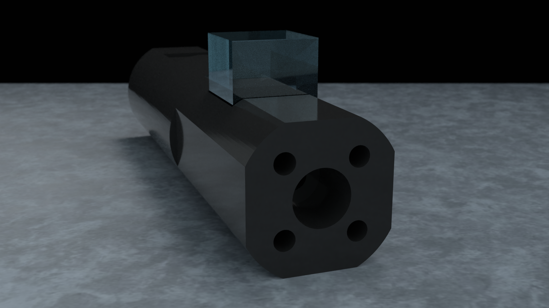
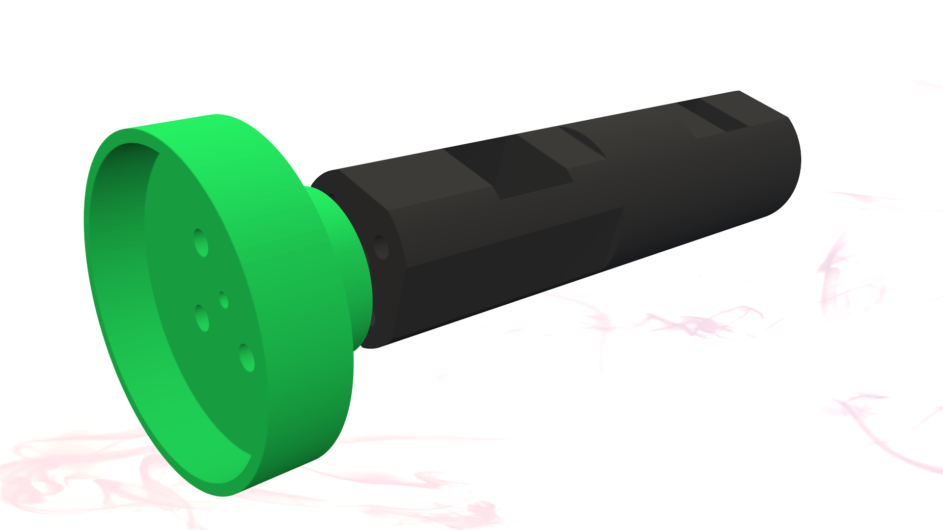
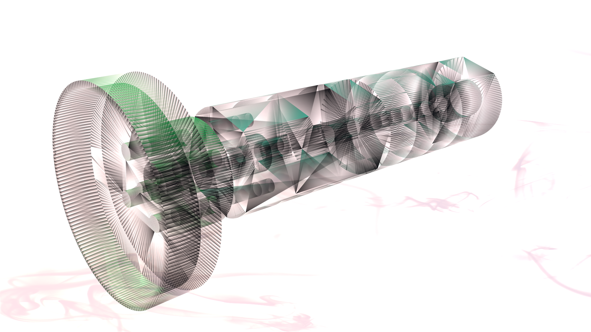
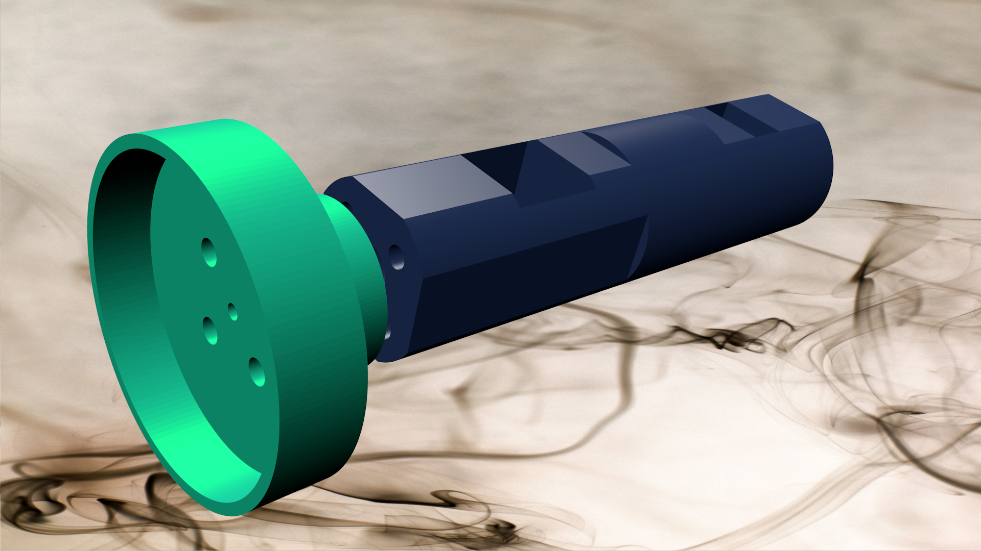
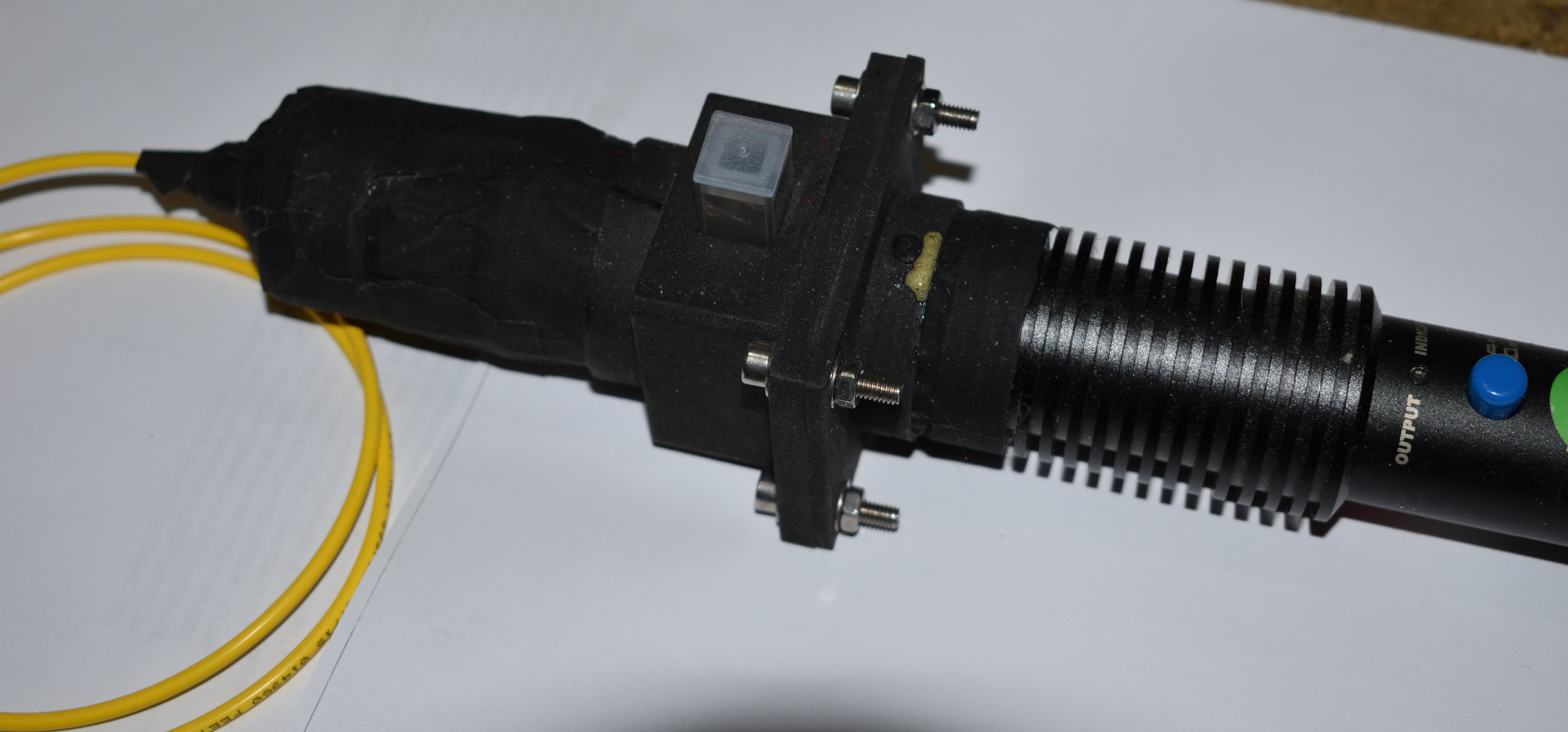
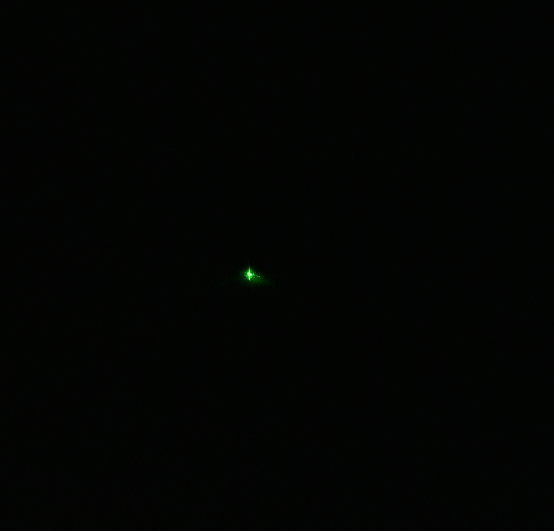
This is my entry into the 2018 Hackaday prize, although I have only 3d printed the inner fiber port as of yet, I have tested the concept to the point where I am comfortable in printing the rest of the design. My main logs are still intact at my original post for this project, and will change as these change.

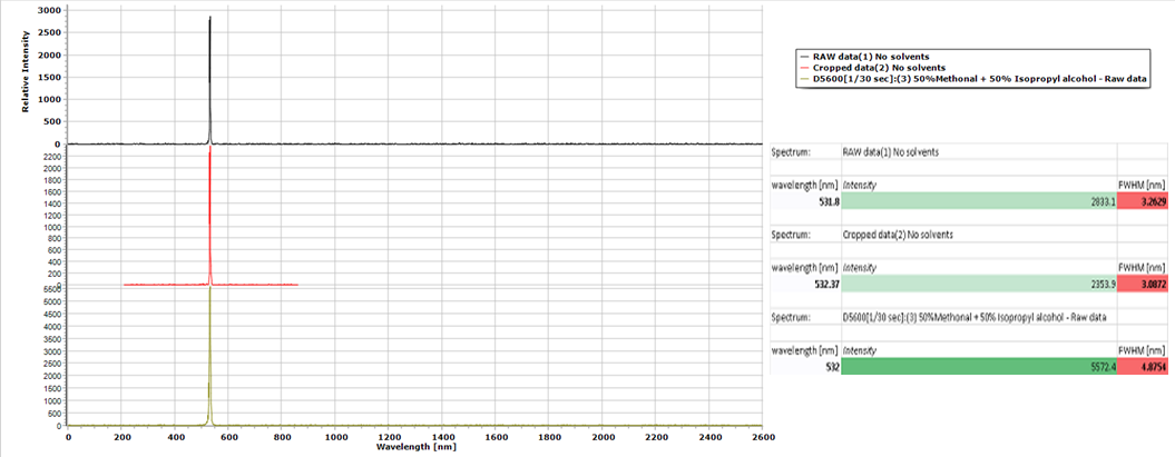
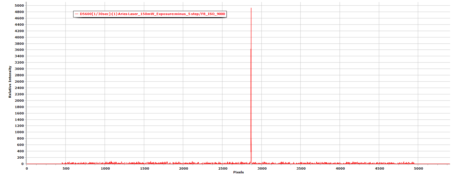
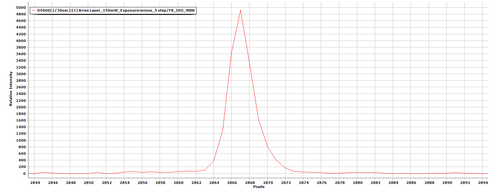
The main detector for this design is a Nikon D5600 DSLR digital camera specifications are below:

Specifications for the Nikon D3400: 

  • Effective Pixels (Megapixels) 24.2 million.
  • Sensor Size. 23.5 mm. x 15.6 mm.
  • Image Sensor Format. DX.
  • Storage Media. SD. SDHC. ...
  • Top Continuous Shooting Speed at full resolution. 5 frames per second.
  • ISO Sensitivity. ISO 100 - 25,600.
  • Movie. Full HD 1,920x1,080 / 60 fps. ...
  • Monitor Size. 3.0 in.

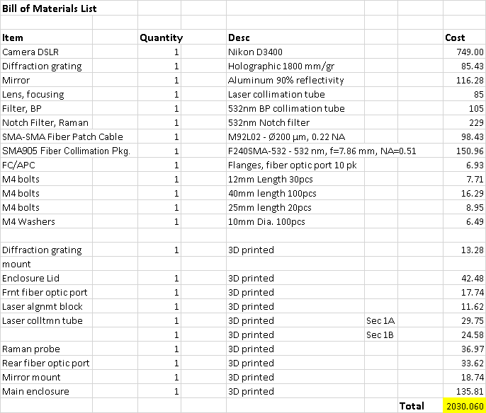
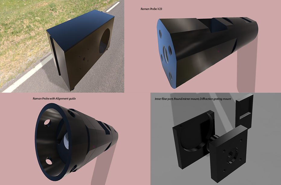
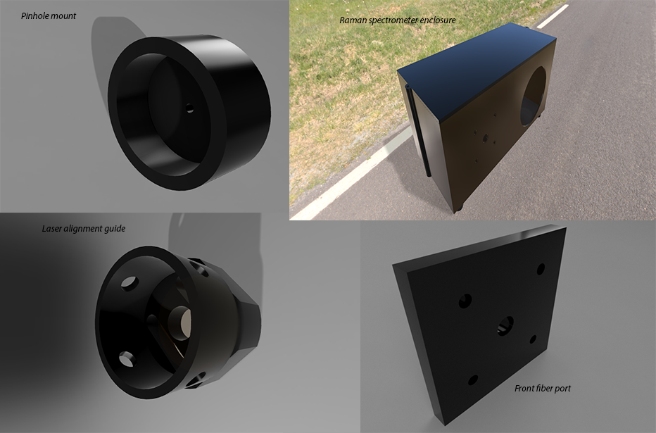
BOM (bill of materials) for The 3D printable Raman Probe v23 project:

There is also a Zip file available in Excel format for download. 

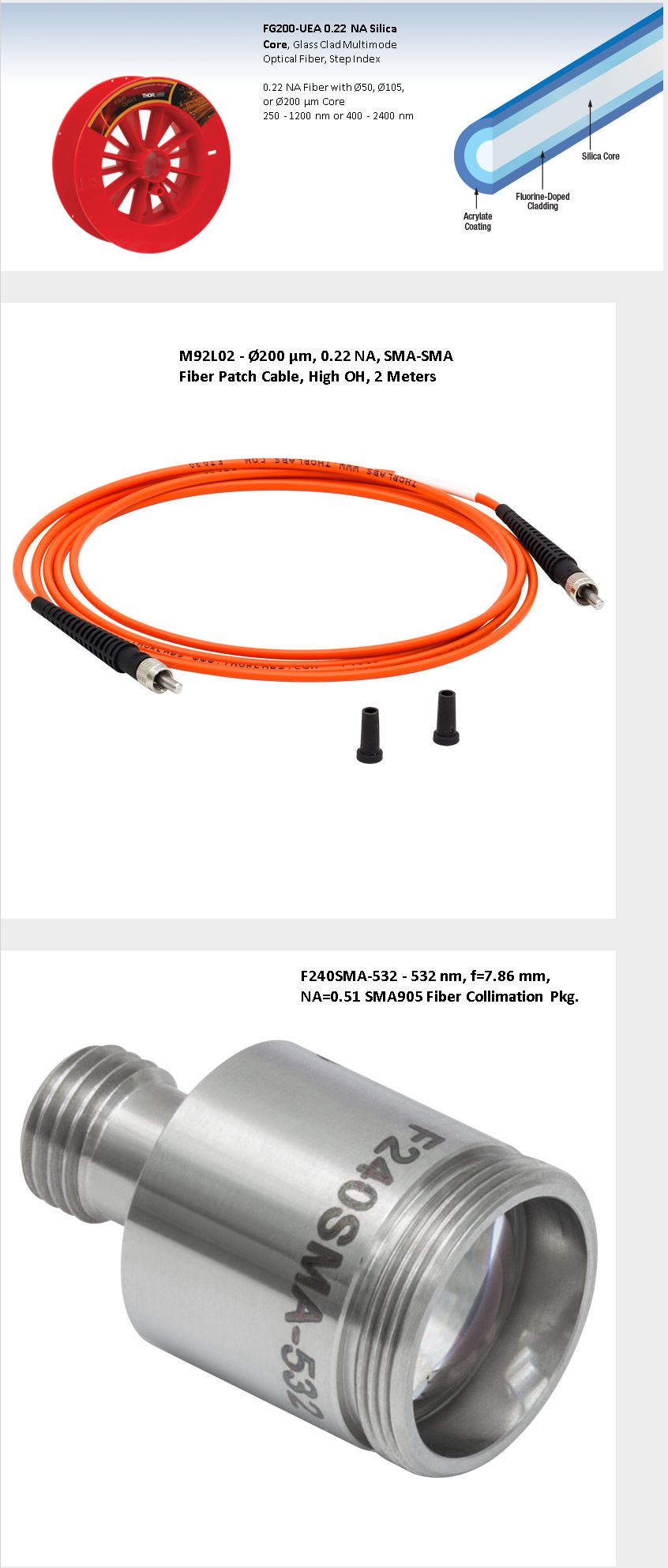
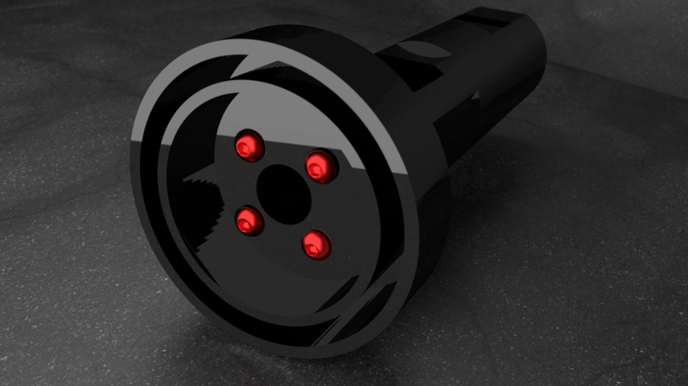
This will be the fiber cable that will be used:

Raman spectroscopy an easy explanation:

Raman spectrometers

These systems consist of:

  • one or more single coloured light sources (lasers)
  • lenses (both to focus the light onto the sample and to collect the scattered light)
  • filters (to purify the reflected and scattered light so that only the Raman light is collected)
  • a means of splitting the light into its constituent colours (normally a diffraction grating or prism)
  • a very sensitive detector (to detect the weak light)
  • a device such as a computer to control the whole system, display the spectrum and enable this information to be analysed

Raman scattering offers significant advantages for the investigation of materials over other analytical techniques, such as x-raying them or seeing how they absorb light (e.g. infrared absorption or ultraviolet absorption).

So as this project progresses to it's final conclusion it's purpose will become clearer, I am removing any creative commons licenses or restrictions to keep in spirit with the heart and soul of open source knowledge, the kind here @ Hackaday we build and distribute everyday of the week, in hopes of building a better world :)

BOM Raman probe MAR15.zip

Bill of materials Updated on: 3/15/2018

x-zip-compressed - 7.98 kB - 03/15/2018 at 22:13

Download

STL Mesh files MAR15.zip

Final STL mesh files for the Raman probe v23 and spectrometer enclosure UPDATED on: 3/15/2018

x-zip-compressed - 263.63 kB - 03/15/2018 at 14:05

Download

  • 1 × *Same components as the main project page*

  • Main 3D Raman Probe Component Section v47

    David H Haffner Sr04/20/2018 at 18:26 5 comments

    I'm making my 3D presentations first in sequential order, this has revealed itself to be a project with many subtle complexities that I'm determined to iron out 1st before printing anything, I just don't have financial means to print "wily nilly" and test every little modification and hope I get it right, so I may be out of this years 2018 prize and that's ok, I'd rather get this right than push it through just for the sake of trying to win something and deliver a 3rd rate product.

    All apologies from my end :)

  • ISO-4762 Hex_Bolt Metric 20mm Length

    David H Haffner Sr04/14/2018 at 16:10 0 comments

    This is the standard Hex bolts that are used for this project...

  • Final Conceptual assembly image for the Raman Probe v47

    David H Haffner Sr04/09/2018 at 12:30 0 comments

    Well, here it is. I'm glad I took some time off of this project to help Daren Schwenke and his interdimentional gun project, it gave me sometime to pull back and re-direct my creativity in another avenue and then return with a fresh perspective for the Raman probe project.

    I was able to revaluate to science of this device and fix some glaring flaws and then re-design the laser alignment guide to properly guide the beam to the fiber collimation assembly at the exit port.

    Now she is ready to be printed and tested next month, I have to integrate this delay due to financial considerations, (sorry.)    

  • Raman Probe & Alignment Guide Rendered In Blender v2.79

    David H Haffner Sr03/25/2018 at 09:00 0 comments

  • Fusion 360 Render_Raman Probe v23.01 & Laser Alignment Guide 5.1

    David H Haffner Sr03/24/2018 at 14:28 0 comments

    Final re-design and render for the Raman probe project, 3D parts to be printed in April:

    1) Laser alignment guide

    2) Raman probe

    3) Pinhole mount

    Once these components are tested I will print the remainder of the components and assemble the complete apparatus and fire her up!

  • Proto_Test Platform Complete Raman Probe v23 using CH4O + C3H8O

    David H Haffner Sr03/18/2018 at 13:02 0 comments

    For anyone wondering what is the point with all these preliminary tests, well, its important because I need the cleanest laser line with the lowest SNR (signal to noise ratio,) possible, even though the Notch filter will block the line, it will not eliminate a poor signal.

    The above image is what I have been using, sort of a "mock-up" of the real probe, without the Notch filter in order to shape the laser line correctly and adjust the DSLR camera settings.

    This was my final SNR test, I used a standard 1cm Quartz cuvette filled with a 50% solution of Methanol and 50% Isopropyl alcohol and an empty cuvette as a blank.

    This zoomed in plot, represents all 3 spectrums in comparision to each other, the first is the raw data (un-processed,) the second is the raw data cropped in RSpec in order to get a more refined signal, the third is the sample withe solvent solution.

    As you may notice there is a noticable difference in intensity, that's because the solvent exibits a higher refractive index as compared to just the refractive index of the empty cuvette, plus there is a higher S1 to S2 energy transfer going on.

    The only problem I can see with this plot is at the peaks you can tell a slight "clipping," to the left, that is camera adjustment territory (exposure and F-stop).

  • 2.9nm Laser Line Resolution

    David H Haffner Sr03/17/2018 at 09:44 0 comments

    UPDATED: 3/17/2018 @ 10:14:AM

    Raw data capture from RSpec:

    Average width of human hair - 17 - 181 um

    The Physics Factbook

    I wanted to also include the raw data comparison plot

    Nikon D5600 camera settings: 

    1) F-stop = 8, shutter speed = 1/30 sec, ISO = 9000, exposure = minus 5 step

    Raw data transferred to Spectragryph spectroscopy processing software

    Below is a zoomed view of the laser line

  • Effects of Pinhole (600um Dia.) on 150mW Laser Transverse Mode TEM00

    David H Haffner Sr03/16/2018 at 14:06 0 comments

    I conducted my 1st official test of my homemade pinhole mount @ 600um diameter, using an 18mm diameter ocean optics slit mount and black-out aluminum masking tape. Using an everyday sewing needle which happens to be 0.61mm in diameter I carefully poked the center of the foil I had fashioned over the mount and these are the results, a very nice quite and stable laser beam with very low SNR (signal to noise ratio,) check it out below:

    The image above can be zoomed in many times for a precise view of the center hole, very straight forward build on this one.

  • Revised Components Rendered Using Fusion 360

    David H Haffner Sr03/15/2018 at 14:08 0 comments

    These are all the final versions and are ready for 3D printing :)

  • Breakthrough On the Laser Alignment Guide Block

    David H Haffner Sr03/13/2018 at 23:14 0 comments

    Well I've been wrong before and I was wrong this time too, I re-examined the original paper that I sited for this project because I felt something wasn't quite right, and I wasn't too far off the mark. What I missed was in their initial setup they have a pinhole diaphram as a beam shaper before the laser strikes the sample, hence forgoing a "real" laser collimator, this actually is still fine (although it would of been better if they would have given the dimensions for the pinhole size, but I figured it out through trial and error...)

    Dimensions are: 0.6mm/0.02" in diameter

    This is the raw jpeg image, zoomed by 50X to show the actual laser point (TEM00)

    Looks awesome huh? Almost like the Sun, if U look close you can see a finger print on the diffraction grating to the far left...oops

    Below is the actual spectrum as seen by the detector

    Below is the plot, the FWHM value (full width half maximum,) of the beam is 1.5nm! 

    The DSLR camera settings were as follows:

    F-stop @ 10

    Exposure time @ 1/30 sec

    ISO @ 7200

    Exposure bias @ -5 step

    35mm focal length

    I am incorporating the pinhole mount to fit into the laser guide component block for the Raman probe and will have a proper build log when I have ALL components printed as I keep re-designing out of  necessity.

View all 10 project logs

Enjoy this project?

Share

Discussions

Similar Projects

Does this project spark your interest?

Become a member to follow this project and never miss any updates