Jan Steinman
This project is specifically for Olympus/Panasonic µ4/3rds mirrorless camera bodies and Olympus OM System lenses, but can easily be adapted to other cameras and lenses.
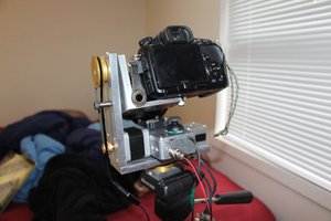
- Design goals are about 150mm of travel, with a minimum distance of 26mm, so lenses can be focused to infinity.
- Main component is a stepper-motor-driven lead screw assembly that is intended for Z-axis use in CNC milling machinery or 3D printers. It is available from multiple US and China sources for about $60.
- The foldy bits of the bellows are salvaged from old 35mm bellows. These are often available used for as little as $5 plus shipping.
- The standards (front an rear portions that the folding material attaches to) are made from scrap aluminum or stainless steel. Aluminum can be carefully worked with woodworking tools with carbide blades. Small bits of such metals can often be salvaged from scrap yards or dumps.
- The lens mount is salvaged from an OM System extension tube, purchased used for $5. Extension tubes for most 35mm camera systems are inexpensive and widely available.
- The camera mount is a modified "reversing ring," which is designed for mounting a lens "backwards" on a camera. The particular one in this project mounts lenses with a 58mm filter to a µ4/3rds body. They are widely available for most camera bodies for under $10, in a few different filter sizes. I used a stationary belt sander to grind the filter threads off, leaving a flat surface that easily mounts to the rear standard with three 2mm countersinking screws.
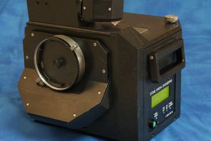
- The controller is an Arduino MEGA with a 3.5" touch-sensitive LCD display.
The software uses a side-view image of the bellows. To change the distance, drag the rear standard. (The front standard is fixed.) The bellows (and display) moves in synchrony. At the proper position, a virtual button allows you to set the begin and end point. Another virtual button allows you to set the step size. A final button makes it all go!
 Kevin Kadooka