-
1Step 1
I ordered 10 board with only these components assembled during pc production. Seeed Fusion services were utilized and I sent them the board Gerber files and this short BOM:
Designator Manufacturer Part Number Quantity C5 16TQC10M 1 C6 T491B106M006AT 1 U2 PCA9685PW/Q900,118 1 U1 TB6612FNG,C,8,EL 1 C1,C2,C3 C2012X8R1H104K125AA 3 R1,R2 ESR10EZPJ104 2 R3,R4,R5,R6,R7,R8,R9,R10,R11 ESR10EZPJ221 9 LED1 LTST-C170KFKT 1 C7 GRM21BR71C105KA01L 1 R12 ESR10EZPJ473 1 I purchased most the other components shown here and assembled my board. A complete BOM is in the files section of this post.
-
2Part Insertion
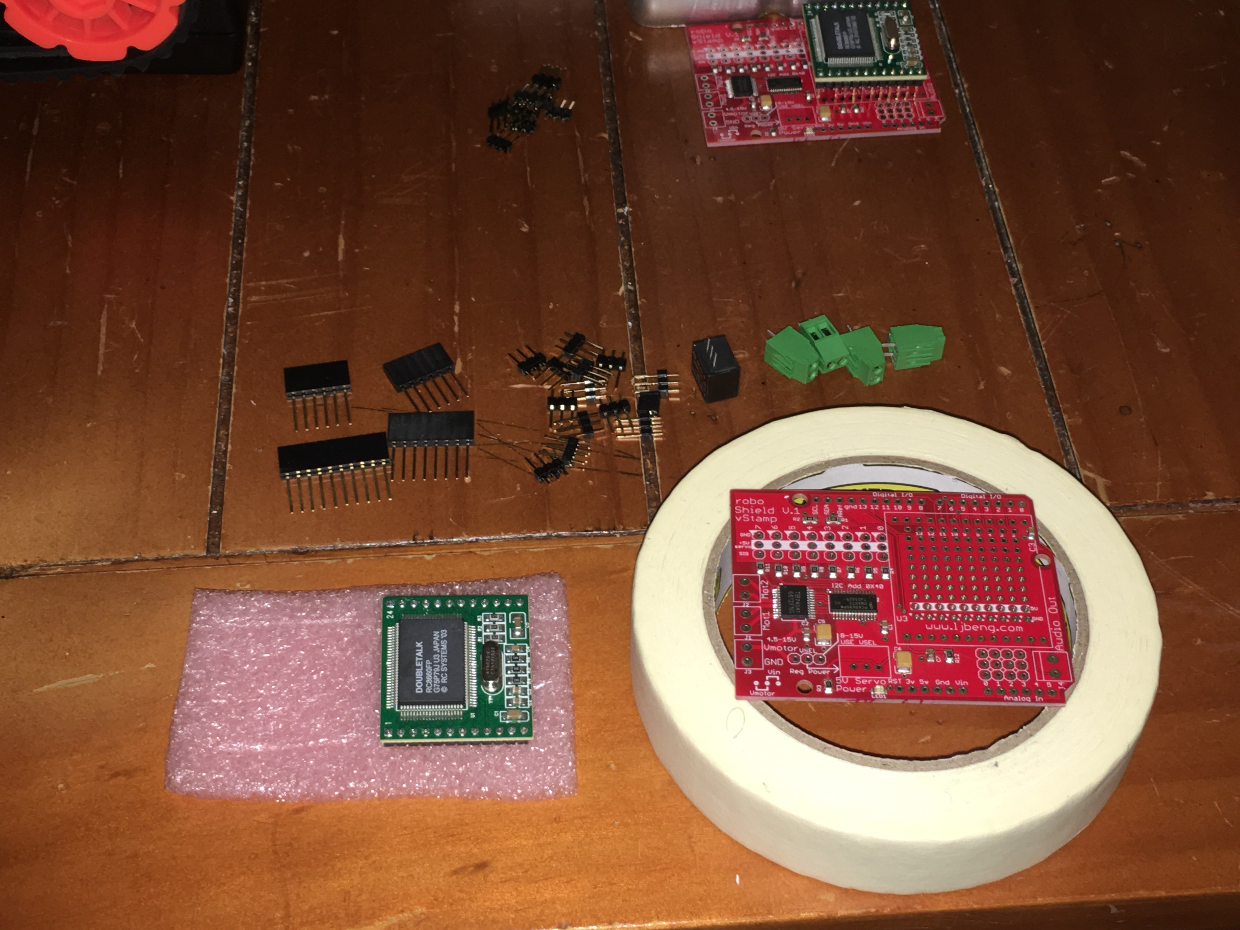
Find a way to raise the board for part insertion. Turn board over and solder each step. I use another blank board to hold the parts down while I flip the board. These photos are in the order you will want to use from shortest to tallest part.
-
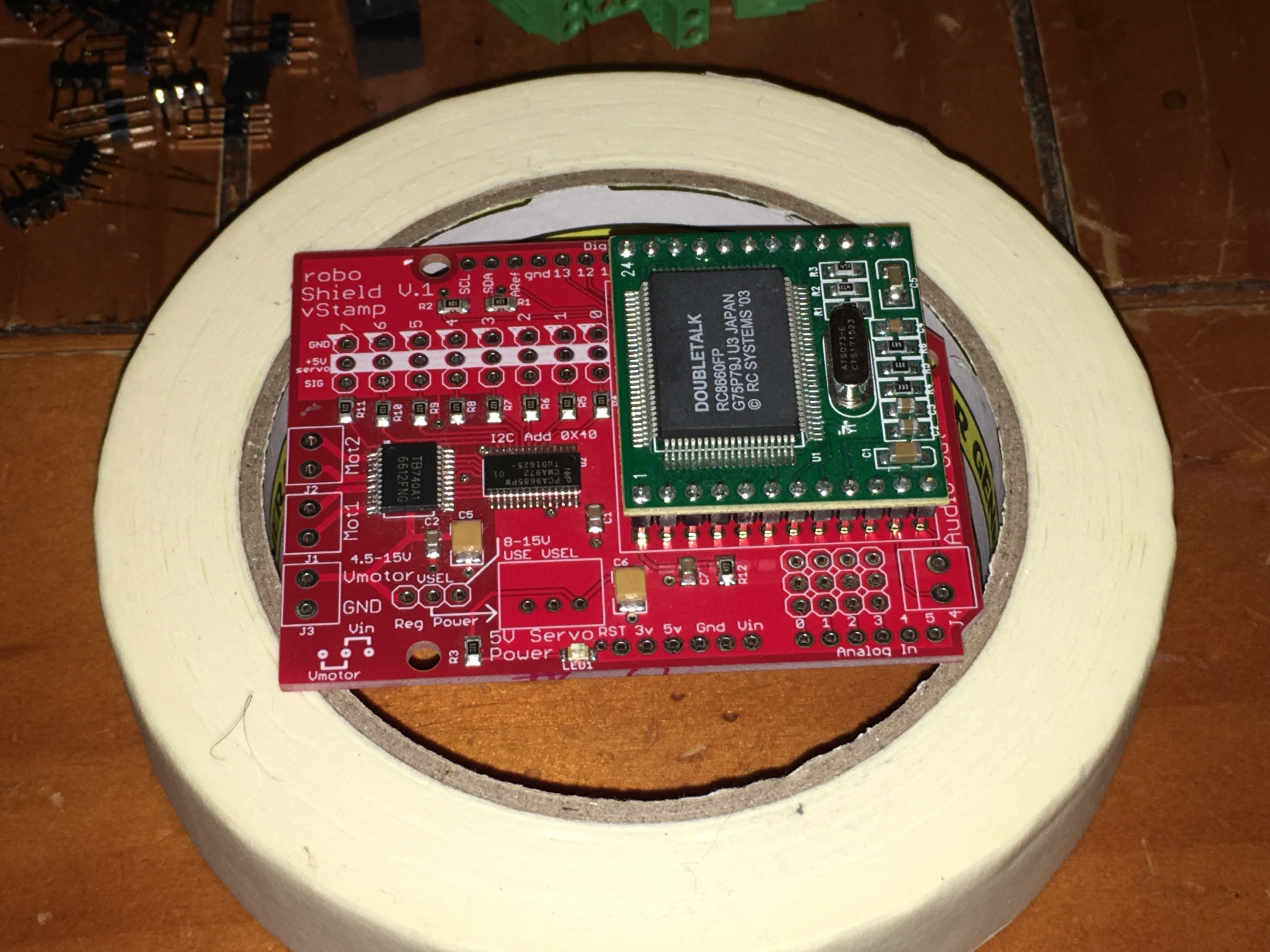
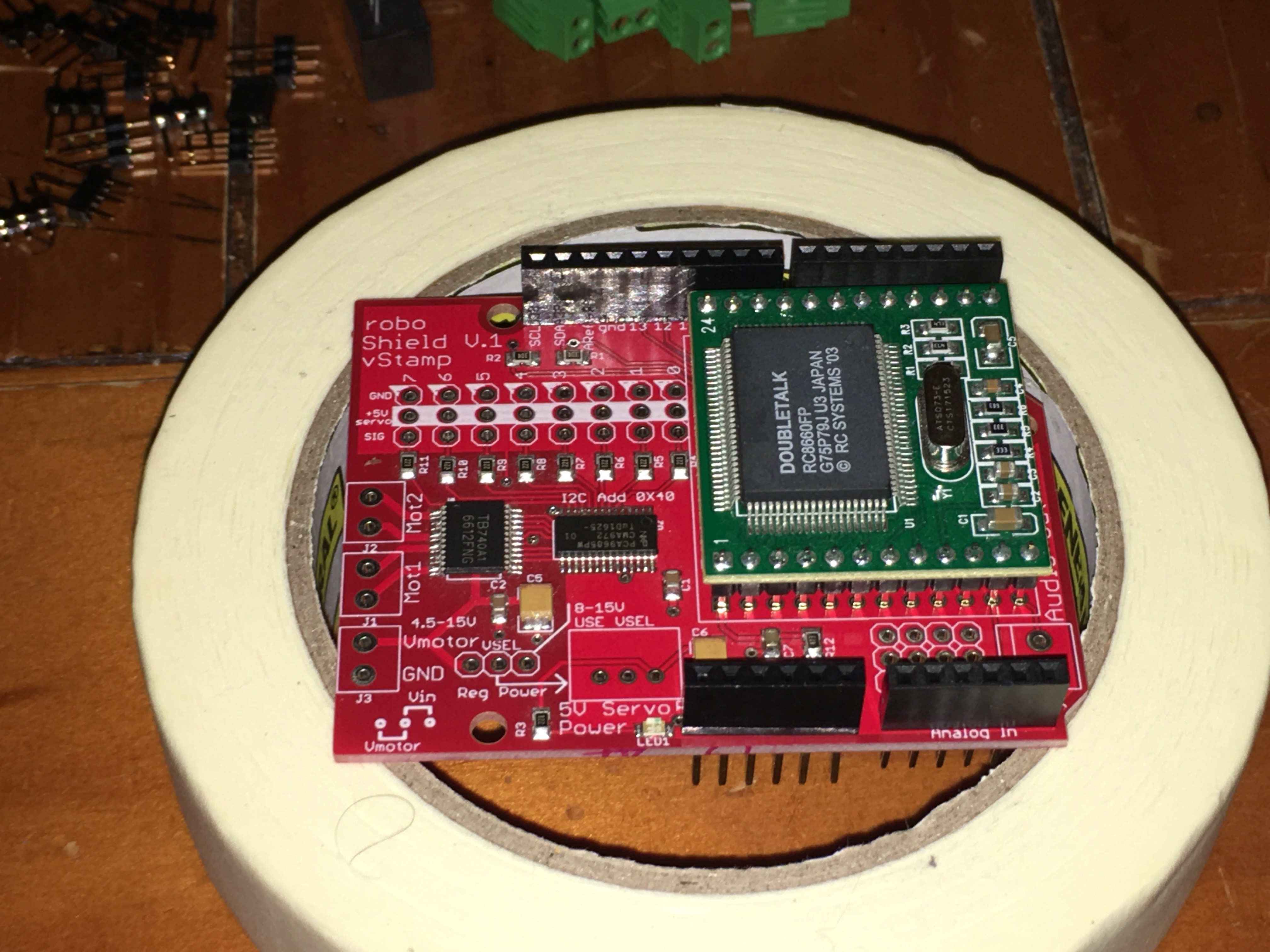
3Add the Arduino Headers first and Vstamp first.
-
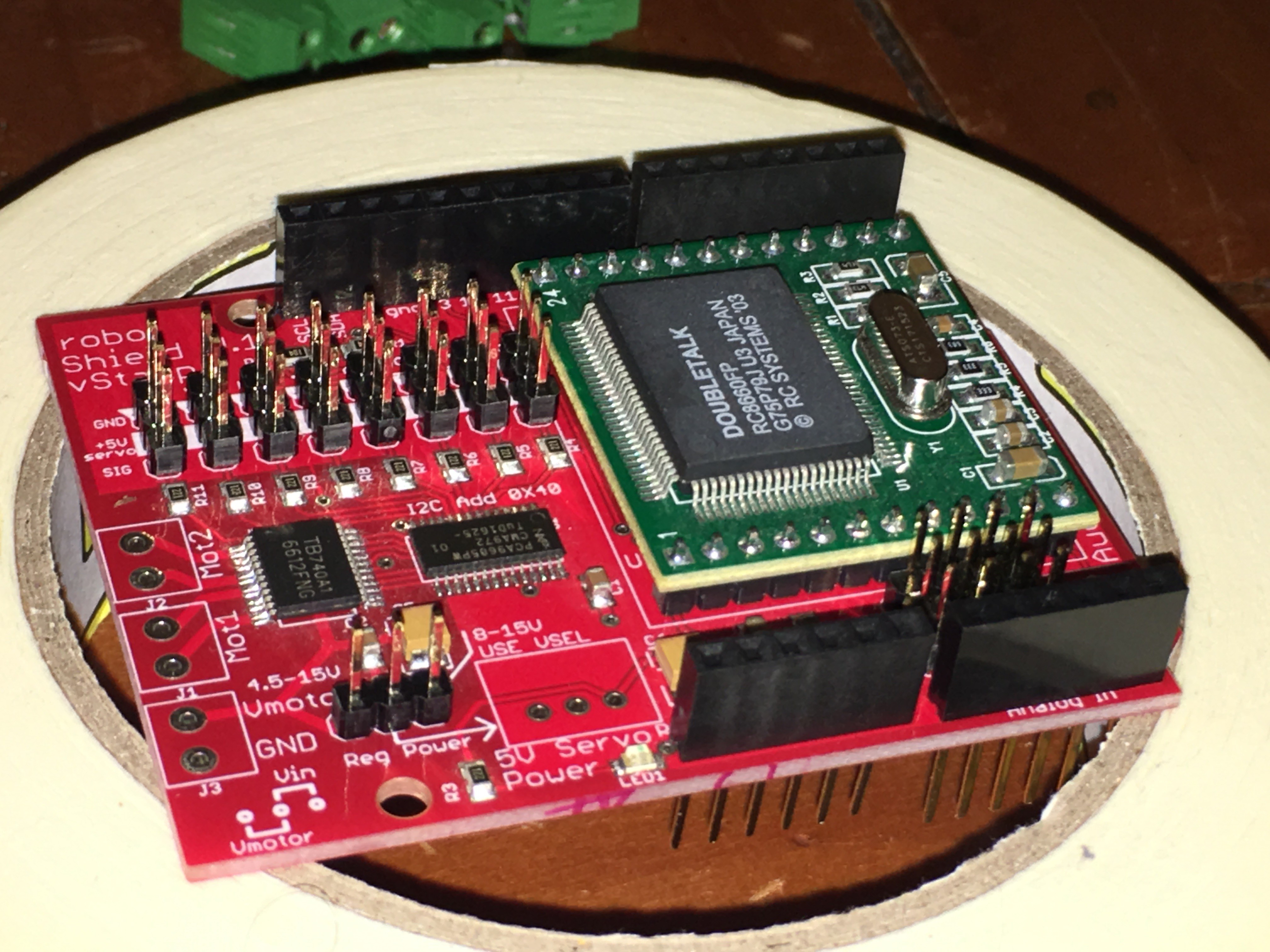
4Next are the servo and analog pins
I ordered some 3 position headers so I didn't have to break apart a header but you need 39 to a single 40 pin header will work just fine for this step
-
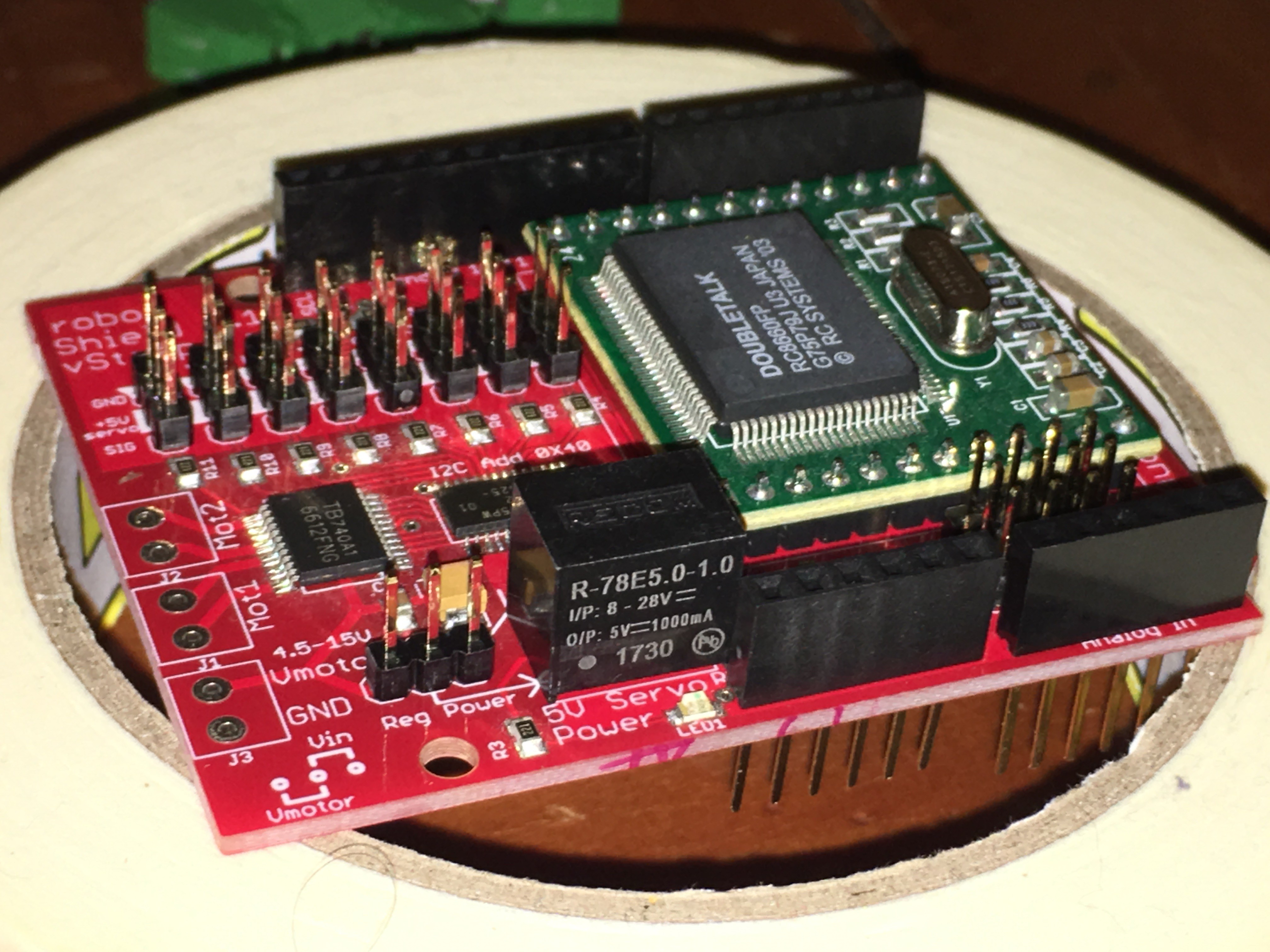
5Next is the 5V switching regulator. Note the orientation...
-
6Last are the screw connectors
roboShield #voice #motor #servo #sensor
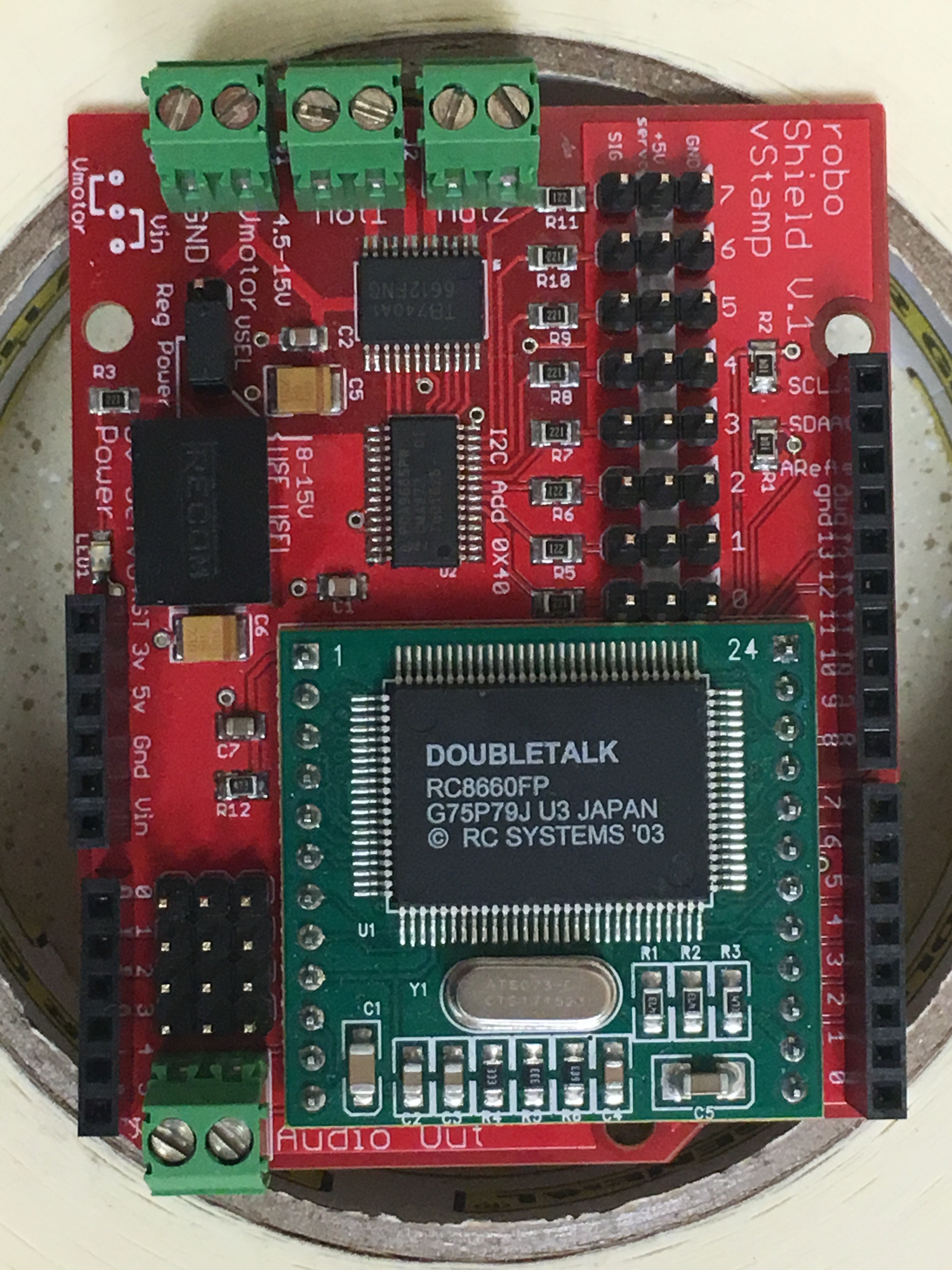
An Arduino Shield that combines True Text To Speech, 2 Motor Controls, 8 Servos and multiple Sensor Inputs
 Luke J. Barker
Discussions
Become a Hackaday.io Member
Create an account to leave a comment. Already have an account? Log In.