Close
0%
0%

DSPIC33 SQI

DSPIC33 square inch dev board.

Similar projects worth following
It needs to be mountable on a breadboard. And fit in 1 square inch.
It will have:
- Interface for the pickit3
- some diagnostic LED's
- dspic33 (of course).
- Removed 3.3 regulator, it won't fit on the board.

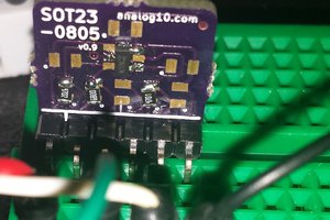
It's a small dev board for experimenting with the DSPIC33 series of chips. I grabbed these a while ago as I wanted to play with both their analog features as well as the JTAG interface. Although I hear the latter is limiting, I though it'd be fun.

Testing.

There's a couple of LED's on the RA0 and RA1 lines respectively; these will be handy for testing. i.e.: the normal "hello world" of blinking a couple of them to test the board.

  • 2 × HEADER10 2.54mm pin header (10P) For I/O, Power, ground. Bottom fed.
  • 1 × HEADER5 2.54mm pin header (5P) - PICKIT programming header. Top fed.
  • 1 × Blue LED - 0805 LED (LiteOn) LTST-C17TBKT
  • 1 × Green LED - 0805 0805 LED (LiteOn) LTST-C171GKT
  • 1 × Button Reset button - Got like 100 of these from Aliexpress.

View all 13 components

  • It's ALIVE!!!

    sutfuf12/17/2015 at 12:17 0 comments

    Bodge wires to the rescue!!! Yeah baby, yeah!!! :-) I've used these before; I have even seen them on consumer products, but, I have never used 14 of them on one chip!

    It works a treat. It took about an hour, soldering under a microscope. I used "wire-wrap" wire, tweezers and I forget how many cokes. ;-) It was like 40 degress C in the lab. (Hot today, it's summer here in OZ.)

    I couldn't sleep last night, I was sooo annoyed I screwed up the footprint, so I decided to use the bodge wires then and there; and since I was up anyway, I baked the board with the components that _did_ fit. :-)

    Btw: The PIC processor differs to the BOM; however, it's pin compatible. (This one has more SRAM) It's a dsPIC33FJ32MC302; The oscillator is only 2MHz, not 10; I have no idea where I put the 10MHz crystals.. they in one of the plethora of parts boxes in the lab's cupboard. I'll use them on the updated board when I get around to it.

  • Fail. Fix later. :-(

    sutfuf12/16/2015 at 23:07 0 comments

    I received the boards from the board house, they look ace... But.. The footprint I used for the SOIC28 (the PIC) is out by 1mm. :-( Usually, when I do my own boards, I have a process to check all this; I rushed it and skipped a few checks on my checklist, one of them was to confirm this footprint. I didnt, and well, it does not fit :-( I might try some bodge wires!!! I wanted this board to run some xmas lights.. So, bodge wires may help me out here. :-) We'll see.

    Due to xmas being around the corner, I dont really have time to fix this and get another board done by the 22nd. I will complete the board as I really need these boards, but, i doubt it will happen before xmas and therefore before the comp ends.

    Sorry all; This comp was ace, and I have actually learnt more doing this than rolling my own boards in my kitchen/garage.

  • Design Files updated

    sutfuf12/07/2015 at 13:34 0 comments

    GitHub repo updated with all design files; i.e.: Schematic, BOM, netlist, PCB source, gerbers and postscript files.

  • Final gerbers sent

    sutfuf12/03/2015 at 14:23 0 comments

    The final gerbers are on there way to the acid baths in china, courtesy of dirtypcbs. Hopefully all goes well and I end up with around 10 boards :-)

  • Erk! A mistake!

    sutfuf12/03/2015 at 01:46 0 comments

    Doh. C3 is in the wrong place. :-( It's connected to the Vcap pin in order to stabilize the internal voltage regulator on the DS33. It should be as close to the Vcap pin as possible. It's miles away! I'll have to move it. Luckily, no etching yet; I decided to sleep on it instead of sending it to the board house last night... As for the DiY etching, I don't like my chances of lining up the bottom layer; I'll give it a go anyway. :-) Everything else looks fine. :-D

  • First Pic!

    sutfuf12/02/2015 at 15:08 0 comments

    Yes, it's a rendering of the gerbers. :-) Generated here: http://mayhewlabs.com/3dpcb

    Hanging to etch it!

  • Where's version 1.0?

    sutfuf12/02/2015 at 15:01 0 comments

    During the first revision of the PCB, I had to remove about 10 extra components, they simply won't fit. I had to sacrifice the 3.3V LD1117 regulator, LED and a couple of transistors. Meh, 3.3V seems to be the go nowadays, so time to get used to it.

    Its a pity the SOIC28 is so big. I didn't want to use the LQFP as it's a waste of I/O pins. i.e.: I can only place so may usable pin headers on the board. Plus I really wanted this board to fit on a bread board, so no weirdness or whacky component placing. :-(

    I probably should have updated this as I went, but I do have a day job, so less time for fun! :-(

    The revision was bumped to 1.1; then after some re-pining of the headers, it was bumped to 1.1a. Unless I spot some glaring mistakes, this should be the final version.

    Due to the extension, I'll probably post all the files tomorrow; it's like 2am here.

View all 7 project logs

Enjoy this project?

Share

Discussions

Blecky wrote 12/07/2015 at 01:15 point

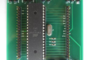
Just a friendly reminder to please upload your design documents by 23:59 UTC on Dec 8, 2015 to be in the running for #The Square Inch Project!

  Are you sure? yes | no

alpha_ninja wrote 12/02/2015 at 00:40 point

This is your one-week reminder to upload design documents: https://hackaday.io/project/7813-the-square-inch-project/log/28566-design-deadline

  Are you sure? yes | no

Similar Projects

Does this project spark your interest?

Become a member to follow this project and never miss any updates